Electrical installation
Parallel connection
Braking units with a common brake resistor
5
l
44
EDBMB935X EN 8.0
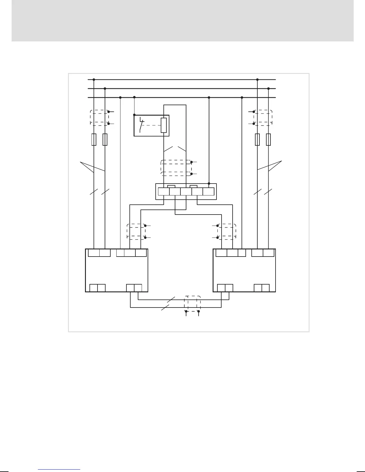
5.4.2 Braking units with a common brake resistor
Maste
r
+UG
-UG
E1
9352
Z1
E2 A1 A2
PE
RB1
RB2
+UG
-UG
PE
F1-F2
Slave
RB1
RB2
E1
9352
Z2
E2 A1 A2
PE
+UG
-UG
F3-F4
Z3
RB1 RB1 RB2 RB2
"
"
"
"
X1
PE
"
"
"
"
"
"
"
"
£
1m, 4mm
2
£
1m, 4mm
2
£
2m
£
2m
£
1m, 4mm
2
£
1m, 4mm
2
0
0
1
JRB
9350br_013
Fig. 10 Parallel operation of 2 brake choppers on one brake resistor
Z1 Brake chopper 1 = master
Z2 Brake chopper 2 = slave
Z3 Brake resistor
F1 ... F4 DC−bus fuses 25 A
X1 Terminal strip
JRB Thermal contact has to be integrated into the temperature monitoring
0 Length difference of the 4 cables: £ 0.05 m
1 Cable length of braking unit − brake resistor: £ 8 m