Electrical installation
Use of brake resistors smaller 27R
Braking units with a common brake resistor
5
l
45
EDBMB935X EN 8.0
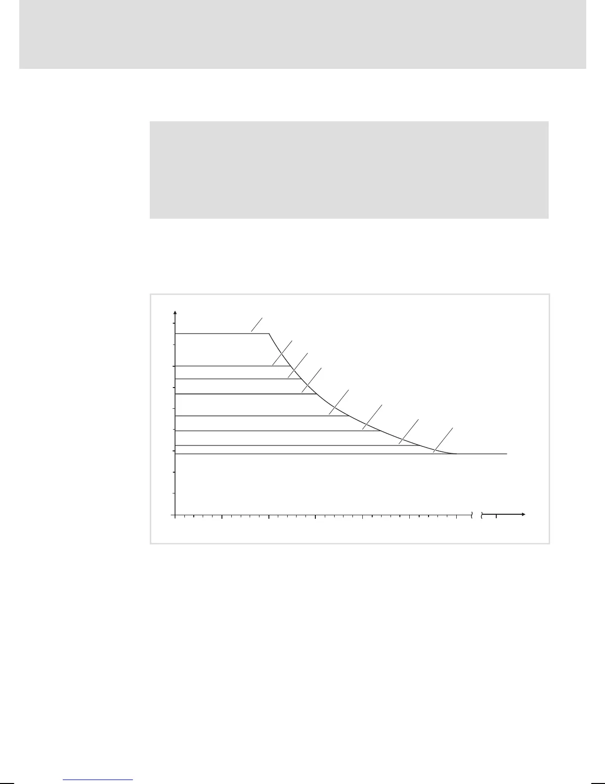
5.5 Use of brake resistors smaller 27R
( Stop!
Failure of the brake chopper if the braking times are exceeded:
ƒ Observe the power of the brake resistor.
ƒ Integrate the temperature monitoring of the brake resistor into
the emergency stop chain.
When using the external brake resistors with the EMB 9352 brake chopper, the
maximum braking times are to be observed.
They result from t
on
+ t
off
= 3 s.
The diagram applies to applications with U
mains
³ 400 V.
I [A]
t [s]
on
0
0
0.5 1.5 2.51.0 2.0 3.0
5.0
15
35
25
45
5
10
30
20
40
Imax_22R
Imax_24R
Imax_27R
Imax_33R
Imax_39R
Imax_47R
I_d
Imax_18R
9350br_014
Fig. 11 Braking current of the EMB 9352brake chopper
I_d Continuous current
t
on
Running time
Example for the determination of the braking times with R
B
= 33 W:
t
on
= 1.83 s; t
off
= 1.17 s.