S94P01C -e1
37
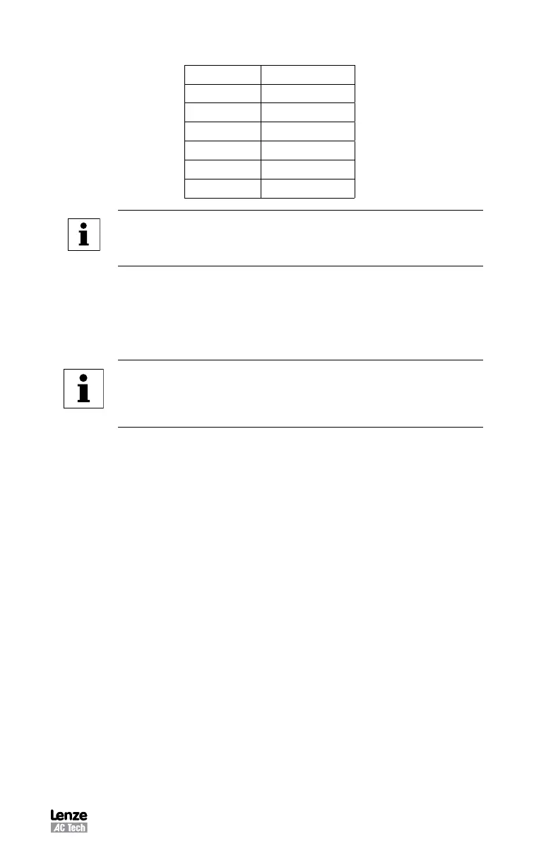
Hall Order Numbers for Different Hall Sequences
Halls Order Hall Sequence
0 1-2-3
1 1-3-2
2 2-1-3
3 2-3-1
4 3-1-2
5 3-2-1
Note
Each Hall Voltage is in phase with one and only one Output Voltage.
B leads A for CW.
This is the encoder phase relationship for CW/CCW shaft rotation. When you obtain
the diagram for your motor phasing similar to shown above, it’s assumed by the
software that the motor shaft rotates CW when looking at the mounting face of the
motor. For that rotation Encoder phase A must lead phase B. If it does leave check
box unchecked. Otherwise (if B leads A ) check B leads A for CW box.
Note
Lenze convention references the shaft direction of rotation from the
front (shaft end) of the motor. Some manufacturers’ timing diagrams
are CW when viewed from the “rear” of the motor.
5.6.3.3 For Resolver Equipped Motors Only:
If parameter “Resolver” is checked, following parameters appear on the form:
Offset in degree (electrical )
This parameter represents offset between resolver’s “0 degree” and motor’s windings
“0 degree”.
CW for positive
This parameter sets the direction for positive angle increment.
“Offset in degree” and “CW for positive” will be set during Auto-Phasing of the motor.
5.6.3.4 For Asynchronous Servo Motors Only:
Four additional parameters need to be defined for asynchronous motors:
Power Factor Cos Phi (cos f)
The power factor is defined as the ratio of the active (true or real) power to apparent
power. The power factor range is from 0 to1.
Base Frequency in Hz
The motor base frequency defines the output frequency, when operating at rated
voltage, rated current, rated speed, and rated temperature.
Velocity Nominal in RPM
Also called rated velocity or speed, velocity nominal is obtained when the motor is
operated at the base frequency, rated current, rated voltage, and rated temperature.
Velocity Max in RPM
This is the maximum speed of the motor. Usually it is limited by mechanical
construction.
 Loading...


