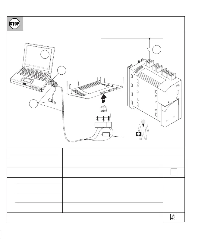
Function control Drive PLC
Make the connection between the PC and Drive PLC and the PC system bus module ONLY when the
equipment is switched off !
0
l
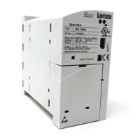
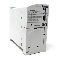
Drive PLC
Developer Studio
GND
LOW
HI
X5
120
+18…30VDC/0V
1
4
3
2
?
82plc017
Step Comment See
c
Connect the PC system bus
module
z Do not forget bus termina ting resistor (120 Ω).
z Follow the instructions for the system bus module.
d
Switch on the supply
voltagefortheDrivePLC.
The permitted voltage is +18 ... 30 V DC
7
e
Switch on the PC Start the Drive PLC Developer S tudio (DDS) software.
Set up the communication
parameters
“Drive PLC Developer Studio - Getting started”,
Chapter 4.4.2
Load the project example “Drive PLC Developer Studio - Getting started”,
Chapter 4.4
Start program “Drive PLC Developer Studio - Getting started”,
Chapter 4.4.4
Are there any faults during commissioning or regular operation ?
?
?