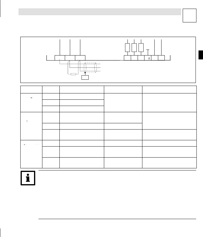
Control connections
P
EDK10200EV3 DE/EN/FR 5.0
QN
L
Terminal strips on the bottom of the instrument
Abb. 1-19
plc003
X4
X5
AI1GND LOW HI AI2
AI3
AOV AOIA
100K
100K
100K
120
CAN-CG
CAN-LO
CAN-HI
PES
Terminal Use Level Data
Analog
X4/AI1 Freely assignable input 1
inputs
X4/AI2 Freely assignable input 2
-10V...+10V Resolution: 10 bit + sign
X4/AI3 Freely assignable input 3
...
Analog
outputs
X4/AOV Voltage output
-10V...+10V/max.
2mA
Resolution: 10 bit + sign
X4/AOI Current output
-20mA...+20mA
ccuracy: ±0.5 %
X4/A⊥ Ground for analog inputs
and outputs
- -
System bus
X5/GND CAN-GND
Reference potential
-
(CAN)
X5/LOW CAN-LOW System bus LOW
(data cable)
-
X5/HI CAN-HIGH System bus HIGH
(data cable)
-
qáé>
z A detailed description of how to invert the digital input and output levels can be
found in the section ”DIGITAL_IO” of the Manual for the Drive PLC Developer Studio
(DDS).
z Use the function block L_AIN or L_AOUT to adjust the analog input and output
signals. A description of this can also be found in the section ”Standard Library
9300 Servo PLC” of the DDS Manual.