Mechanical installation
Mounting
Attachment of motors to gearboxes with bearing housing
4
l
23
BA 12.0023−EN 6.0
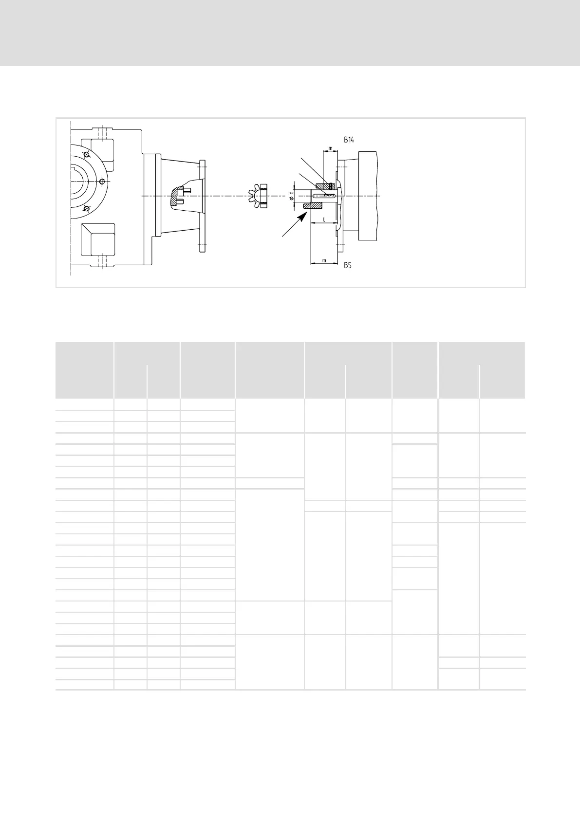
4.4.4 Attachment of motors to gearboxes with bearing housing (input design N)
1
2
0
1
K12.0621
Fig. 3 Input side design N
0 Spider / gear rim 1 Locking screw
1 Coupling hub 2 Keyway
Drive size
Motor shaft Assembly
dimension
Standard hub
Locking screw
Clamping hub Key
1)
Clamping ring hub
D
[ mm ]
max. l
[ mm ]
M
[ mm ]
Thread
[ mm ]
Thread
[ mm ]
Tightening
torque
[ Nm ]
DIN
6885/1
[ mm ]
Thread
[ mm ]
Tightening
torque
[ Nm ]
1A 11 23 23
M4 M3 1.34 * M3 1.34
1B 14 30 30
2B 11 23 23
1C 19 40 25
M5
M6 10.5
B6 x 6 x 16
M4 2.9
2C 14 40 25
B5 x 5 x 16
3C 14 40 25
4C 14 40 25
6C 11 40 25 −−− * −−− −−−
7C 19 40 25
M5
B6 x 6 x 16 M4 2.9
1D 24 50 50 M4 2.9
*
−−− −−−
2D 19 40−50 50
M6 10.5
M4 2.9
1E 28 30−60 30
B8 x 7 x 18
M5 6
2E 24 30−60 30
3E 19 30−60 30 B6 x 6 x 18
4E 24 50 50 *
1F 28 30−60 30
B8 x 7 x 18
2F 24 30−60 30
3F 24 50 50
*
1G 38 80 80
M6 M8 25
2G 28 60 60
3G 38 80 80
1H 42 110 110
M8 M10 69 *
−−− −−−
2 h 48 110 110
3H 38 80 80 M8 35
1K 55 110 110
−−− −−−
2K 60 140 140
Tab. 3 Attachment of motors to gearboxes with mounting flange
* Use original key for the motor
1)
Key for standard hub and clamping hub