Electrical installation
EMC−compliant wiring
Power connections on the terminal board
6
30
Lenze ¯ BA 33.0008 ¯ 5.0
6.3.1 Power connections on the terminal board
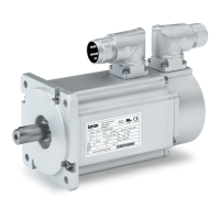
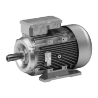
Motor
Multivoltage motors
M50AP, M55AP M54AP
L1
L2
L3
V5
U1
V1
W1
U5
W5
U2
V2
W2
L1
L2
L3
U1
V1
W1
U5
W5
U2
V2
W2
V5
L1
L2
L3
V3
U1
V1
W1
U3
W3
U2
V2
W2
L1
L2
L3
U1
V1
W1
U3
W3
U2
V2
W2
V3
MT_MXXXX_001.iso/dms
Legend for the circuit diagrams
L1/L2/L3 Power connection
UU Low voltage
U High voltage
Temperature monitoring
Terminal strip / terminal board
Contact Meaning Note
(1)TB1
Thermal contact − TCO
Max. 250 V~
Max. 1.6 A ~
(1)TB2
(1)TP1
PTC thermistor
(1)TP2
(1)R1 Thermal sensor +KTY
Observe polarity
(1)R2 Thermal sensor −KTY
Terminal board or terminal possible for all thermal sensors.
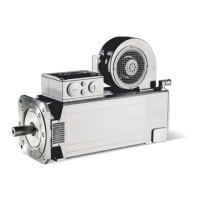
Blowers via blower terminal box / motor terminal box
Blower 3~
Terminal board
Contact Meaning Note
U1
Connection to L1 −
mains
Observe direction of rotation! In case of wrong direction of
rotation, L1 − L2 must be interchanged
V1
Connection to L2 −
mains
W1
Connection to L3 −
mains
Separate fan 1~
Terminal board
Contact Meaning Note
U1 Connection to L1 − mains
V1 / U2 Connection to N − mains
 Loading...