Maintenance/repair
Installation of a spring−applied brake
Assembly of the friction plate, sizes 06 to 16
8
52
Lenze ¯ BA 33.0008 ¯ 5.0
8.4.4 Assembly of the friction plate, sizes 06 to 16
15
2
7
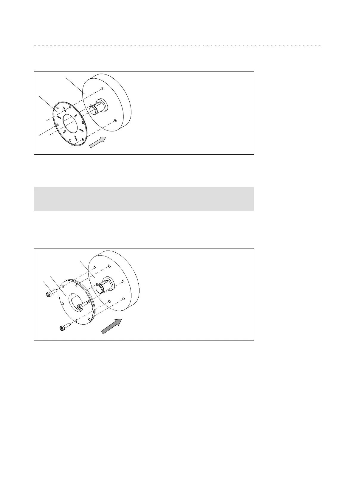
KL458−009−a
Fig. 6 Friction plate mounting
15 End shield 27 Friction plate
1. Put a friction plate (27) or flange (6) against the end shield (15).
) Note!
The flanged edge of the friction plate must remain visible!
2. Align pitch circle and fastening bore hole thread.
8.4.5 Assembly of the flange
15
6
6.1
KL458−008−a
Fig. 7 Flange mounting
6 Flange 15 End shield
6.1 Set of screws
1. Hold the flange (6) against the end shield (15) and check the pitch circle and
retaining screw drill hole threading.
2. Fasten the flange (6) on the end shield (15) with the screws (6.1).
3. Tighten the cheese head screws (6.1) evenly, (tightening torques (¶ 49).
4. Check the height of the screw heads. The screw heads may not be higher than the
minimum rotor thickness. We recommend using screws according to DIN 6912,
dimensions (¶ 49.
 Loading...