Electrical installation
Three−phase AC motor operation on a frequency inverter
6
29
Lenze ¯ BA 33.0008 ¯ 5.0
6.2 Three−phase AC motor operation on a frequency inverter
m500−P, m540−P, and m550−P three−phase AC motors are optimised and qualified for
the use on Lenze frequency inverters and can be combined without any restrictions.
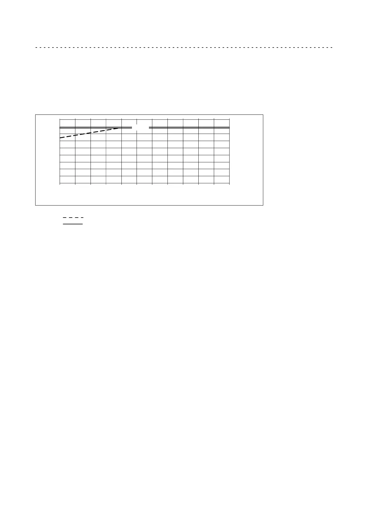
When actuating the motors on a third−party inverter, the voltage peaks (V
pk
) at a
given rise time (t
R
) that are shown in the diagram must not be exceeded.
0.2
0.4
0.6
0.8
1.0
1.2
0
0.2
0.4
0.6
0.8
1.0
1.2
1.4
1.6
1.8
1.56 kV
t
r
(s)m
U
pk
(kV)
0.1
0.3 0.5
0.7
0.9 1.1
MT−m500−001.des
Fig. 1 Permissible voltage peaks for actuation on the frequency inverter
IEC/TS 60034−25:2007 (corresponds to IVIC C/B/B @500 V): m540−P
Lenze standard A+: m500−P, m550−P
Possible counteractive measures
If it cannot be excluded that the permissible voltage peaks are exceeded, suitable
counteractive measures have to be implemented:
¯ Reduction of the DC−bus voltage (threshold for brake chopper voltage);
¯ Use of filters, chokes;
¯ Use of special motor cables.
6.3 EMC−compliant wiring
The EMC−compliant wiring of the motors is described in detail in the operating
instructions for the Lenze inverters.
¯ Using metal EMC cable glands with shield connection.
¯ Shield connection at the motor and the device.
¯ Shield connection at the terminal strip encoder.
 Loading...