Electrical installation
Plug connectors
Feedback system
6
32
Lenze ¯ BA 33.0008 ¯ 5.0
6.3.3 Feedback system
Resolver
Contact Name Meaning
B1
B2
+ Ref
− Ref
Transformer windings
(reference windings)
B3 Not assigned
B4
B5
+COS
−COS
Stator winding cosine
B6
B7
+SIN
−SIN
Stator winding sine
B8 Not assigned
Incremental encoder / sin/cos absolute value encoder with Hiperface
Terminal Designation Meaning
B1
B2
+ U
B
GND
Supply +
Mass
B3
B4
A / + COS
A
/ Ref cos
Track A / process data channel
Track A inverse / process data channel
B5
B6
B / + SIN
B
/ Ref sin
Track B / process data channel
Track B inverse / process data channel
B7
B8
Z / data +
Z
/ data −
Zero track / parameter channel + RS485
Zero track inverse / parameter channel − RS485
B10
1)
Shield − housing Shield − incremental encoder
1) The terminal is not assigned if insulation at N−end shield of the motor has been selected!
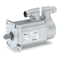
6.4 Plug connectors
Only for m500−P / m550−P
( Stop!
¯ Tighten the coupling ring of the connector.
¯ If plugs without SpeedTec bayonet nut connectors are used, the
connector boxes for the power / encoder / fan connections must be
secured by O−rings if loadings by vibration occur:
– M17 connector box with O−ring 15 x 1.3 mm
– M23 connector box with O−ring 18 x 1.5 mm
Plug−in connectors (plug/connector box) with SpeedTec bayonet nut
connectors are vibration−proof.
¯ If SpeedTec bayonet nut connectors are used, O−rings must be
removed (if any)!
¯ Never disconnect plugs when voltage is being applied! Otherwise, the
plugs could be destroyed! Inhibit the inverter before disconnecting the
plugs!
 Loading...