Electrical installation
Plug connectors
Motor plug connection assignment
6
33
Lenze ¯ BA 33.0008 ¯ 5.0
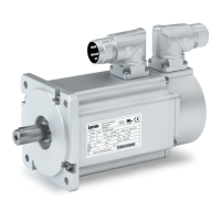
When connecting the cable connector to the motor connector, make sure that the aids
to orientation (pos. 1) are facing each other. Only then trouble−free operation is ensured.
6.4.1 Motor plug connection assignment
) Note!
When making your selection, the motor data and permissible currents of
the cables according to the "System cables" system manual must be
observed.
6.4.2 Power connections
Power / brake / thermal sensor
ICN, 6−pole and 8−pole
6−pole (external view of poles)
Contact Name Meaning M23
1
2
BD1 / BA1
BD2 / BA2
Brake + / ~
Brake − / ~
MT plug−in
−
1
2
4
5
6
+ PE PE conductor
4
5
6
V
V
W
Power phase U
Power phase V
Power phase W
8−pole (external view of poles)
Contact Name Name M23
1 V Power phase U
MT plug−in
connector−001.iso
dms
4
1
A
B
C
D
+ PE PE conductor
3 W Power phase W
4 V Power phase V
A
B
TB1 / TP1 / R1
TB2 / TP2 / R2
Thermal sensor:
TCO / PTC / + KTY
TCO / PTC / − KTY
C
D
BD1 / BA1
BD2 / BA2
Brake + / AC <250 V
Brake − / AC <250 V
 Loading...