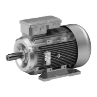
Motor connecon
Mains connecon X3
Pin assignment for QUICKON connector
Conta
ct
Name Meaning
1 L1 Mains connecon Phase L1
2 L2 Mains connecon Phase L2
3 L3 Mains connecon Phase L3
4 PE PE conductor
Pin assignment for M15 connector
Conta
ct
Name Meaning
1 L1 Mains connecon Phase L1
2 L2 Mains connecon Phase L2
3 L3 Mains connecon Phase L3
PE PE PE conductor
A Not assigned
B
Note for the orientaon of a right-angle plug:
The posion of the contact "2" at the terminal box is in the direcon of the terminal box cover.
Terminal assignment in the terminal box
Conta
ct
Name Meaning
1 L1 Mains connecon Phase L1
2 L2 Mains connecon Phase L2
3 L3 Mains connecon Phase L3
PE PE PE conductor
NOTICE
In the "DI/DO-GND bridged" version, the masses of the control terminal X1 and X2 (GND-I and GND-O) are
connected to each other. If only one speed is used, the connecon to X2 is sucient.
Control terminal X1
Pin assignment for M12 connector A coded, pins
Conta
ct
Name Meaning
1 n.c.
2 DI2 Digital input 2
3 GND-I Mass of digital input
4 DI1 Digital input 1
Control terminal X2
Pin assignment for M12 connector A coded, pins
Conta
ct
Name Meaning
1 24V 24 V-supply (DO1 supply)
2 DI3 Digital input 3 (reference X1;3 = GND-I)
3 GND-O Mass of digital output
4 DO1 Digital output 1
Electrical installaon
Motor connecon
60
 Loading...