EasyManua.ls Logo

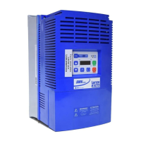
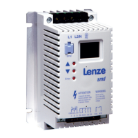
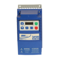
Lenze SMVector User Manual

Lenze SMVector
62 pages
To Next Page IconTo Next Page
Page #1 background imageLoading...
Page #1 background image
Operating Instructions
SMVector - Frequency Inverter
Phone: 800.894.0412 - Fax: 888.723.4773 - Web: www.actechdrives.com - Email: info@actechdrives.com

Other manuals for Lenze SMVector

Questions and Answers:

Lenze SMVector Specifications

General IconGeneral
Protection ClassIP20
Overload Capacity150% for 60 seconds
Communication OptionsCANopen, Profibus DP
Protection FeaturesOvercurrent, Overvoltage, Undervoltage, Overtemperature, Short Circuit
Control MethodSensorless Vector
Ambient Temperature-10°C to +40°C

Summary

Safety Information

General Safety Precautions

Covers handling, operation, installation risks, and qualified personnel requirements.

Installation Safety

Guidelines for safe installation, avoiding mechanical stress and environmental hazards.

Electrical Connection Safety

Observing national regulations for electrical installation and EMC compliance.

Application Safety

Using the drive as a safety device, emergency stops, and automatic restart.

Explosion Proof Applications

Policy on warranty and liability for explosion proof motor applications.

Operation Safety

Systems require additional monitoring and protection devices for safe operation.

Safety Notifications and Signal Words

Understanding icons, signal words (DANGER, WARNING, STOP, NOTE), and their consequences.

Harmonics Notification EN 61000-3-2/3-12

Limits for harmonic current emissions and required compliance measures.

Safety Information EN 61800-5-1

Electrical shock hazard from charged capacitors and PE conductor current.

Safety Information UL Compliance

UL warnings for circuit capability, wire type, pollution degree, and plenum rating.

Technical Data

Standards and Application Conditions

Conformity, approvals, voltage imbalance, humidity, temperature, and enclosure ratings.

SMV Type Number Designation

Explains the structure of the SMVector inverter model number.

Ratings

Specifications for 120V/240VAC, 240V single/three phase, 400-480VAC, and 600VAC models.

Installation

Dimensions and Mounting

Physical dimensions and mounting screw details for NEMA 1 (IP31) models.

NEMA 1 (IP31) Models < 30HP Dimensions

Detailed dimensions and conduit hole specifications for NEMA 1 models.

NEMA 1 (IP31) Models > 30HP Dimensions

Dimensions and mounting details for larger NEMA 1 models.

NEMA 4X (IP65) Models Dimensions

Physical dimensions and conduit hole specifications for NEMA 4X models.

NEMA 4X (IP65) with Disconnect Switch Dimensions

Dimensions and conduit hole details for NEMA 4X models with a disconnect switch.

Electrical Installation

Covers storage, power connections, motor connections, and wiring diagrams.

Fuses and Cable Cross-Sections

Recommendations for fuses, circuit breakers, and power wiring for various SMV models.

Control Terminals

Descriptions of control terminal strips and their functions for different HP ranges.

Commissioning

Local Keypad and Display Functions

Explains keypad buttons (START, STOP, ROTATION, MODE) and display indicators.

Control Source and Mode Selection

Configuring start/reference control sources and drive operating modes.

Parameter Setting and EPM Usage

Overview of parameter setting, using the EPM, and basic setup parameters.

I/O Configuration and Setup

Configuring digital inputs, outputs, and their functions.

Advanced and PID Parameter Configuration

Setting advanced parameters, PID control, and analog input configurations.

Vector Control and Network Parameters

Configuring vector modes, motor data, and network communication settings.

Diagnostic and Sequencer Parameters

Monitoring diagnostics, faults, and configuring sequencer operation.

Sequencer Flow Diagram (Left)

Illustrates the logic for starting segments based on digital inputs and P100/P700 settings.

Sequencer Flow Diagram (Right)

Shows sequence actions, repeat cycles, suspend logic, and end segment control.

Sequencer Status

Displays the active segment, output voltage, and segment delay status.

Troubleshooting and Diagnostics

Status and Warning Messages

Lists drive status/warning codes, their causes, and remedies.

Drive Configuration Messages

Explains the 4-digit codes indicating drive configuration and stop sources.

Fault Messages Overview

Lists common fault codes (F_AF, F_AL, F_CF etc.) with their causes and remedies.

Fault Messages (Continued)

Details on faults like F_dbF, F_EF, F_FI, F_FOL, F_HF, F_IL, F_n Id.

Fault Messages (Continued)

Covers faults F_OF, F_OF I, F_PF, F_rF, F_SF, F_UF, F_FAU.

Appendix A

Permissible Cable Lengths

Table showing maximum permissible cable lengths for SMV models with internal EMC filters.

Related product manuals