43
SV01N_13418587 EN/DE/ES/FR/IT/PT
Commissioning
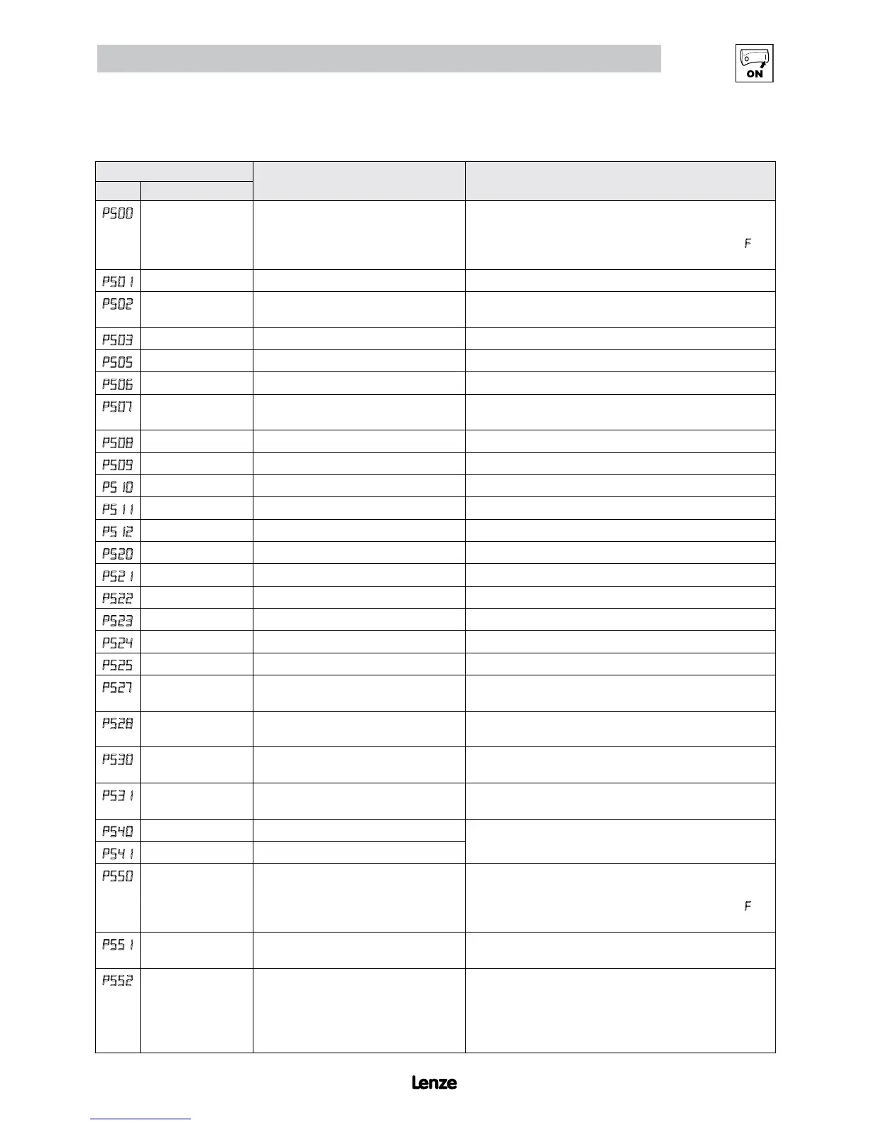
4.5.7 Diagnostic Parameters
Code
Display Range (READ ONLY) IMPORTANT
No. Name
p500
Fault History • Displays the last 8 faults
• Format: n.xxx where: n = 1..8,
1 is the newest fault; xxx = fault message (w/o the
F.)
• Refer to section 5.3
P501
Software Version Format: x.yz
P502
Drive ID A flashing display indicates that the Drive ID stored in the EPM
does not match the drive model it is plugged into.
P503
Internal Code Alternating Display: xxx-; -yy
P505
DC Bus Voltage 0 {VDC} 1500
P506
Motor Voltage 0 {VAC} 1000
P507
Load 0 {%} 255 Motor load as % of drive’s output current rating.
Refer to section 2.3.
P508
Motor Current 0.0 {A} 1000 Actual motor current
P509
Torque 0 {%} 500 Torque as % of motor rated torque (vector mode only)
P510
Output Power kW 0.00 {kW} 650.0
P511
Total kWh 0.0 {kWh} 9999999 Alternating display: xxx-; yyyy when value exceeds 9999
P512
Heatsink Temp 0 {°C} 150 Heatsink temperature
P520
0-10 VDC Input 0.0 {VDC} 10.0 Actual value of signal at TB-5 (See P162)
P521
4-20 mA Input 0.0 {mA} 20.0 Actual value of signal at TB-25 (See P162)
P522
TB-5 Feedback P204 P205 TB-5 signal value scaled to PID feedback units (See P162)
P523
TB-25 Feedback P204 P205 TB-25 signal value scaled to PID feedback units (See P162)
P524
Network Feedback P204 P205 Network signal value scaled to PID feedback units
P525
Analog Output 0 {VDC} 10.0 Refer to P150…P155
P527
Actual Output
Frequency
0 {Hz} 500.0
P528
Network Speed
Command
0 {Hz} 500.0 Command speed if (Auto: Network) is selected as the speed
source
P530
Terminal and
Protection Status
Indicates terminal status using segments of the LED display.
(Refer to section 4.5.7.1)
P531
Keypad Status Indicates keypad button status using segments of the LED
display. (Refer to section 4.5.7.2)
P540
Total Run Time 0 {h} 9999999 Alternating display: xxx-; yyyy when value exceeds 9999
P541
Total Power On Time 0 {h} 9999999
P550
Fault History 1 8 • Displays the last 8 faults
• Format: n.xxx where: n = 1..8,
1 is the newest fault; xxx = fault message (w/o the F.)
• Refer to section 5.3
P551
Fault History Time 0 {h} 999999 Display: “n.hh-” “hhhh” “mm.ss” = fault #, hours, seconds
The “hhhh” screen is displayed after hours exceed 999.
P552
Fault History Counter 0 255 Number of sequential occurrences of a fault.
For example: 3 external faults occur over a period of time
with no other errors occurring. Then P552 will indicate 3,
P550 will indicate the error EF and P551 will indicate the
time of the first fault occurrence.