10
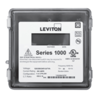
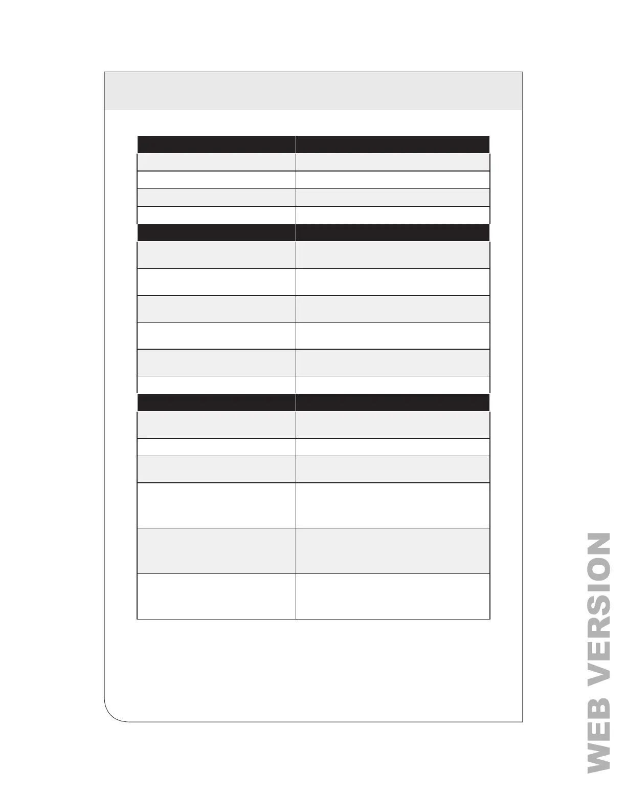
2 TECHNICAL SPECIFICATIONS
Voltage Inputs Description
L3 Voltage Input Line 3
L2 Voltage Input Line 2 (3-wire and 4-wire models only)
L1 Voltage Input Line 1
N Neutral Input (Meter powered from L1 & N)
CT Inputs (J1, Left Side)
CT3: X1 Current Transformer input CT3 Colored wire of CT3
(4 wire models only)
CT3: X2 Current Transformer input CT3. White wire of CT3
(4 wire models only)
CT2: X1 Current Transformer input CT2. Colored wire of CT2
(3-wire and 4-wire models only)
CT2: X2 Current Transformer input CT2. White wire of CT2
(3-wire and 4-wire models only)
CT1: X1 Current Transformer input CT1. Black or colored wire
of CT2
CT1: X2 Current Transformer input CT2. White wire of CT1
CT Inputs (J1, Right Side)
10, Isolated Output (10 Wh/P, Kh = 10 Isolated pulse output: 5 watt/hours on, 5 watt/hours
off, referenced to ISOL COM
COM, Isolated Output Isolated common for 10/1000 isolated outputs
1K, Isolated Output (1 kWh/P, Kh = 1000) Isolated pulse output: 500 watt/hours on, 500 watt/
hours off, referenced to ISOL COM
1 kWh LED (D3 – Green) 50% duty cycle (at constant load) LED with a pulse
rate of 1 kWh per on/off cycle (500 watt/hours on,
500 watt/hours off). In the absence of a significant
load, the LED could be on or off.
10 Wh LED (D2 – Green) 50% duty cycle (at constant load) LED with a pulse
rate of 10 Wh per on/off cycle (5 watt/hours on,
5 watt/hours off). In the absence of a significant load,
the LED could be on or off.
Reverse Phase LED (D1 – Red) Illuminates when a problem with meter phasing
exists. In the absence of a significant load, the LED
could be on or off. See section 3.7 for CT installation
instructions.
Table 3 - I/O Connections and Status Indicators