13
3 INSTALLATION INSTRUCTIONS
3.3 Preparation
• Verify the model number and electrical specifications of the device being installed
to confirm they are appropriate for the intended electrical service (see Section 2).
• Consult local codes for any possible permits or inspections required before
beginning electrical work.
• Ensure the conduit for the installation is appropriate for the intended application.
UL Type 4x conduit and conduit fittings are required for outdoor applications.
• Make sure all tools to be used during installation have proper insulation ratings.
• Look at the meter and inside the electrical panel for possible exposed wire, broken
wire, damaged components or loose connections.
3.4 List of Materials
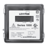
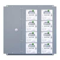
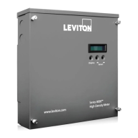
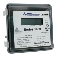
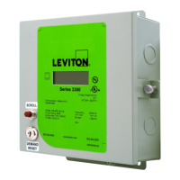
• Series 1000 or Series 2000 meter, enclosure, and associated mounting materials
• Line 1, Line 2, Line 3 and Neutral hookup wires, as needed for the electrical
service
• Wires must be 18 AWG or larger and insulated for 600 VAC min. Meter terminals
will accept wiring up to 14 AWG.
• Current Transformers (CTs): This product is designed for use with Leviton 100mA
series of solid and split core CTs.
• Conduit and fittings, as appropriate. UL Type 4X conduit and fittings must be used
for outdoor applications to maintain the rating of the installation.
3.5 Mounting the Enclosure
3.5.1 Selecting a Mounting Location
• Series 1000 and 2000 meters require a switch or circuit breaker as part of the
building installation.
• The switch or circuit breaker must be marked as the disconnecting device for
the meter.
• It is recommended that the enclosure be mounted near the disconnecting device
in an area with adequate ventilation.
• The enclosure should not be positioned in a manner that makes it difficult to
operate the disconnecting device.
• Ensure that the CT and voltage lead lengths (and conduit lengths) are capable
of reaching the enclosure from the load center.
• If a suitable mounting location near the load center cannot be found, additional
in-line fuses or circuit breaker may be required in accordance with
NEC regulations.