EasyManua.ls Logo

Levitronix LEVIFLOW LFS Series User Manual

Default Icon
31 pages
To Next Page IconTo Next Page
Page #1 background imageLoading...
Page #1 background image
User Manual for LEVIFLOW
®
LFS Flowmeters
www.levitronix.com
PL-4502-00, Rev11, DCO# 18-107
First Release: 29-May-09
Last Update: 30-Jul-18
LEVIFLOW
®
LFS FLOWMETERS
USER MANUAL
LEVIFLOW
®
Sensors: LFS-04(H), -08(H), -20(H), -50(H), -80(H) (LFS-Series)
LFS-008 (Low-Flow Sensor)
LEVIFLOW
®
Converters: LFC-1C (single channel, LFS-Series without LFS-008)
LFC-1C-F4 (single channel, LFS-008 only)
LFC-6C (6-channel, LFS-Series without LFS-008)
LFC-6CIO (6-channel, I/O interface, LFS-Series)
This manual contains information necessary for the safe and proper use of the LEVIFLOW
®
LFS flowmeter series.
Included are specifications for the standard configuration, components, and instructions regarding its use, installation,
operation, adjustment, inspection and maintenance. For special configuration of the LEVIFLOW
®
flowmeters refer to
accompanying information. If the flowmeters have to be configured for other parameter settings then the LEVIFLOW
®
Configuration Software (see relevant manual Levitronix
Doc.# PL-4501-00) is necessary. Please familiarize yourself
with the contents of this manual to ensure the safe and effective use of this product. After reading, please store the
manual where the personnel responsible for operating can readily refer to it at any time.

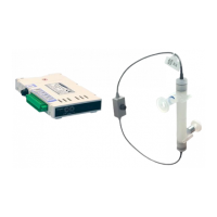
Table of Contents

Questions and Answers:

Levitronix LEVIFLOW LFS Series Specifications

General IconGeneral
Accuracy±1% of full scale
Repeatability±0.5% of full scale
Power Supply24 VDC
Flow Range0.03 - 12 l/min
Pressure RatingUp to 5 bar
Output SignalRS-485
Wetted MaterialsPFA, PTFE
MaterialPFA, PTFE

Summary

Safety Precautions

Specifications

Component Overview

Overview of the different components of the LEVIFLOW® LFS flowmeter system with images.

Standard System Configurations

Diagram and description of single and multi-channel LEVIFLOW® LFS flowmeter system configurations.

Specifications of Sensors

Detailed technical specifications for various LEVIFLOW® LFS sensor models, including flow range and temperature.

Specifications of Converters

Technical specifications for LEVIFLOW® LFC converters, covering power, interfaces, and configuration.

Overview of Parameter Configuration

Details on default and possible parameter configurations for LEVIFLOW® flowmeters using software.

Dimensions of Sensors

Detailed dimensional drawings and tables for LEVIFLOW® LFS flow sensor models.

Dimensions of Converters

Detailed dimensional drawings and mounting concepts for LEVIFLOW® LFC converters.

Dimensions of Adaptor Cables

Dimensional information for LEVIFLOW® adaptor cables used for connecting sensors and converters.

Installation

Installation of Converters LFC-1C and LFC-1C-F4

Instructions for installing single-channel LEVIFLOW® LFC-1C and LFC-1C-F4 converters.

Instructions for Electrical Installation

Detailed steps for making electrical connections to LEVIFLOW® converters, including wiring and grounding.

Configuration of Sensor Specific Data

Procedure for configuring sensor specific data on LEVIFLOW® converters for accurate measurements.

Instructions for Mechanical Installation

Steps for mechanically mounting LEVIFLOW® LFC-1C converters onto a DIN rail.

Installation of Converters LFC-6C and LFC-6CIO

Instructions for installing LEVIFLOW® LFC-6C and LFC-6CIO converters, covering preparation and electrical/mechanical steps.

Overview and Preparation

Overview of components and preparation steps for installing LEVIFLOW® LFC-6C and LFC-6CIO converters.

Instructions for Electrical Installation

Electrical connection instructions for LEVIFLOW® LFC-6C and LFC-6CIO converters, including wiring and EMI ferrite.

Instructions for Mechanical Installation

Steps for mechanically mounting LEVIFLOW® LFC-6C/LFC-6CIO converters and stacks on a DIN rail.

Installation of Sensors

Guidance on installing LEVIFLOW® sensors, including electrical connections, mechanical mounting, and hydraulic considerations.

Overview and Preparation

Overview of LEVIFLOW® flow sensor models and preparation for installation, including calibration data.

Instructions for Electrical Installation

Steps for connecting LEVIFLOW® flow sensors to converters, ensuring proper IP-65 protection.

Instructions for Mechanical and Hydraulic Installation

Guidance on mounting LEVIFLOW® flow sensors, considering flow direction, vibrations, and fluid conditions.

Operation

General Timing Specifications

Timing specifications for LEVIFLOW® converters, including startup, thermal stability, and zero adjustment.

System Operation with LFC-1C / LFC-1C-F4

Details on system operation of LEVIFLOW® LFC-1C/LFC-1C-F4 converters with PLC, RS485, and standalone display.

Display Messages

Explanation of display messages shown on LEVIFLOW® LFC-1C/LFC-1C-F4 converters for status and errors.

System Operation with Converter LFC-6C and LFC-6CIO

Details on operating LEVIFLOW® LFC-6C/LFC-6CIO converters via PLC, RS485, standalone display, and understanding their display messages.

Operation with LEVIFLOW Configuration Software

Using LEVIFLOW® Configuration Software for debugging, data collection, and configuring flowmeter systems.

Inspection and Maintenance

Periodic Checks for Operation

Recommended periodical checks for LEVIFLOW® ultrasonic flowmeters to ensure smooth and reliable operation.

Troubleshooting

Common Troubles

Table of common phenomena, their possible causes, and countermeasures for LEVIFLOW® flowmeters.

Troubleshooting with LEVIFLOW Configuration Software

Using LEVIFLOW® Configuration Software for detailed error analysis and troubleshooting.

Technical Support

Appendix

Regulatory Status

Information on CE marking and conformity with EMC and Pressure Equipment Directives for LEVIFLOW® flowmeters.

CE Marking

Details on LEVIFLOW® flowmeters conforming to EMC Directive 2014/30/EC and Pressure Equipment Directive 97/23/EC.

Symbols and Signal Words

Explanation of safety symbols, signal words (DANGER, WARNING, CAUTION), and their meanings.

Related product manuals