4.2 System Operation with LFC-1C / LFC-1C-F4
4.2.1 Standard Operation with PLC Interface
Table 10 shows the standard configuration of the electrical interface (PLC). For other configurations the
LEVIFLOW
®
configuration software has to be used (according manual is Levitronix
Doc.# PL-4501-00).
4.2.2 Typical Setups Using the PLC Interface
The Figure 23 and Figure 24 show typical setups for LEVIFLOW
®
converters using the PLC interface.
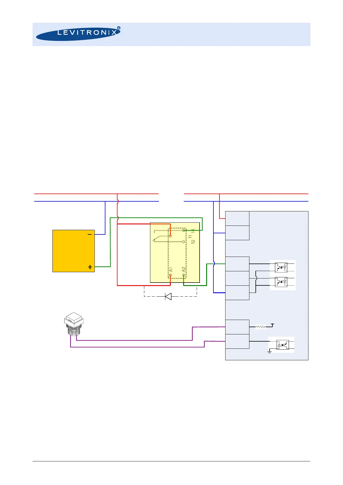
Figure 23 is an example how to connect the LEVIFLOW
®
converter to a relays to control a shutoff valve by a
digital output. Note that if protective diode is normally not integrated within relays it has to be connected
additionally as shown in Figure 23. This setup additionally shows how to connect a push-button to digital
input (e.g. for reset of volume counter, which has to be configured with LEVIFLOW
®
configuration software).
Figure 23: Controlling a shutoff valve by digital output of LFC-1C-xx converters
Figure 24 shows an example how to connect digital in-/outputs and analog output of LFC-1C-xx to a
Levitronix
®
Pump System.
 Loading...

