User Manual for LEVIFLOW
®
LFSC-iX Flowmeters
www.levitronix.com
PL-5001-00, Rev00, DCO# 21-084
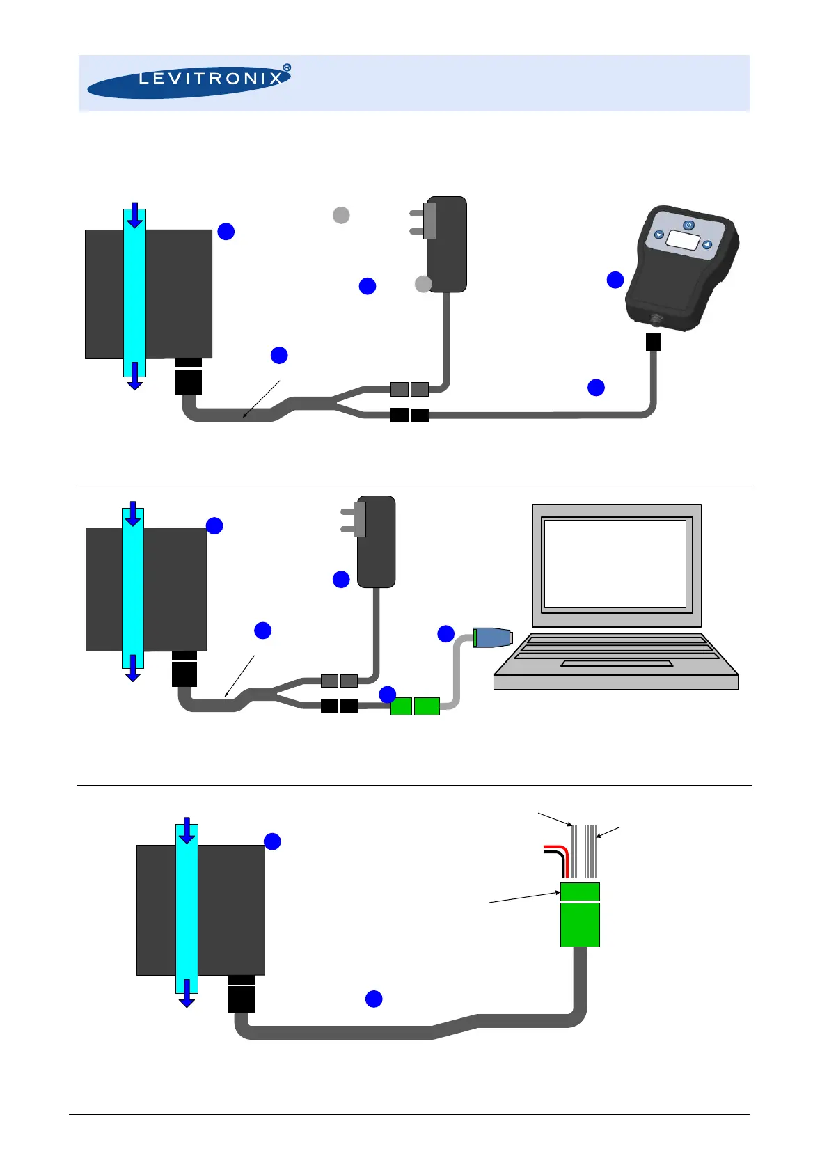
2.2 Standard System Configurations
Figure 3: Stand-Alone system configuration
(See section “Order Information” for details to numbered components and other options)
Figure 4: Configuration for PC with Levitronix
®
Service Software (parameter configuration, Data logging and monitoring)
(See section “Order Information” for details to numbered components and other options)
Figure 5: OEM system configuration
(See section “Order Information” for details to numbered components and other options)
Flow In
Flow Out
LEVIFLOW
®
Clamp-On
Flowmeter
LFSC-iX
Series
Splitting Cable
User Panel
LUI-B.1
AC/DC Supply
International
Mains Insert
Interconnect Cable
(Direct connection possible.)
Flow In
Flow Out
LEVIFLOW
®
Clamp-On
Flowmeter
LFSC-iX
Series
Splitting Cable
AC/DC Supply
International
Mains Insert
Levitronix
®
Service Software
Configuration
Service/Firmware Update
Data Logging/Monitoring
USB to RS485
Converter with Cable
Flow In
Flow Out
LEVIFLOW
®
Clamp-On
Flowmeter
LFSC-iX
Series
OEM Cable
PLC:
2x Analogue Output
2x Digital Output
1x Digital Input
Screw type connector for
open-wires connection
included in cable package.
DC Supply
Fieldbus
(RS485 Modbus)