User Manual for PuraLev
®
i30SU
www.levitronix.com
PL-4051-00, Rev03, DCO# 20-275
State “Off”:
The pump system is switched off and the motor has no power. In this state, Levitronix
®
Service Software has
full control.
State “ON” (speed control mode):
The pump system is switched ON and the impeller is rotating with the referenced speed. The motor has
electrical power when in this state.
State “ON” (process control mode):
The pump system is switched ON and the impeller is rotating with the referenced flow/pressure. The motor
has electrical power when in this state.
On (Priming mode):
The pump system is switched ON and the impeller is rotating with the priming speed. The motor has
electrical power when in this state. This mode can only be accessed by activating priming feature within
EEPROM-editor in Levitronix
®
Service Software. Priming speed and timeout can also be configured within
EEPROM-editor.
State “Error”:
If an error according to Table 14 occurs in the pump system, the system defaults to the Error state. The
according digital output on the PLC Interface Module is activated. The pump system is switched OFF. By a
pulse off 300-700 ms on the Enable/Reset input the system gets back to the Off state.
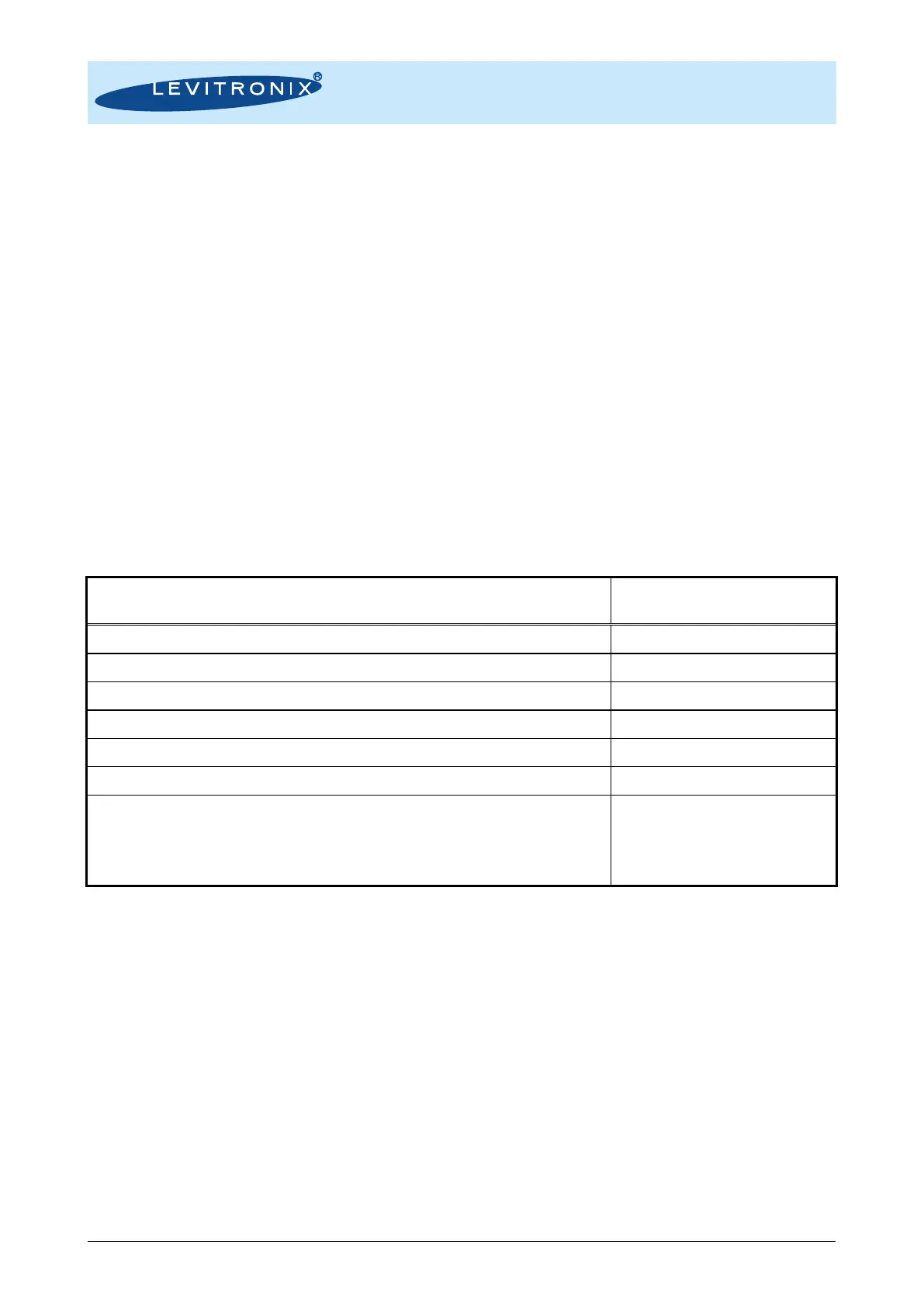
Effect on Designated
Digital Output of the PLC
Temp. was higher than 80°C for more than 10 minutes.
Power channel interrupted
Internal sensor cable interrupted
DC link (supply voltage) out of range (< 18 or > 30 V DC)
If the voltage is out of range the system starts to reduce the speed and a warning is
generated. When reaching 0 rpm and the voltage is still out of range the system is disabled
and an error is generated. In case the voltage is again within the range during speed
reduction the system switches to normal operation and no Error is generated.
Table 14: Errors with indication on PLC interface for standard firmware
(For other configurations refer to alternate firmware documentation)
5.2.2 Operation with Fieldbus (RS485)
See Section 4.3.5.
5.2.3 Operation with User Panel LUI-B.1
The RS485 interface can also be used with the user panel LUI-B.1, which has the same menu functions as
the Stand-Alone model (described in Section 5.1). The relevant configurations are illustrated in Figure 7 for
the OEM and in Figure 5 for the EasyConnect driver models.
5.2.4 Operation for Serial Pumping
See Section 4.2.7.