4
3- Installation instructions
Kit includes the following parts:
DESCRIPTION NUMBER
Handbook 1
Installation instructions 1
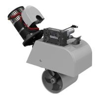
Bowthruster with motor and tube 1
Bolts for connecting the motor 4
Washers for connecting the motor 4
Stop plate for brace* 1
DESCRIPTION NUMBER
Drive shaft 1
Plastic shear pin for actuator (spare) 1
Metal shear pin for thruster (spare)* 1
Fuse holder 1
Fuse 1
*Not for model 250
Start by marking out the centre line on the outside of the hull, e.g. by sighting between a point right forward and
the keel. Using the 3mm hole drilled in step 3.1 as a centre point, mark the outline of the hatch using the dimen-
sions in the table below.
140 Thruster Width = 220 mm Length = 274 mm
185 Thruster Width = 255 mm Length = 346 mm
250 Thruster Width = 375 mm Length = 480 mm
The bowthruster should be placed as far forward as possible, without the top of the box coming above the
waterline, otherwise it could be difficult to fit or remove the motor. Measure out the most suitable location from
inside the boat. Drill a 3 mm hole as close as possible to the centre line, within the area in which the hatch will
eventually sit. This hole will be used as a reference point for locating the mould on the outside of the hull. The
installation kit does not include the mould, since the mould must be manufactured on site in order to fit the
shape of the hull of your boat.
3.1 Mark out the position fore and a
3.2 Placing the mould
⚠ ATTENTION!
DO NOT power the motor flange with the actuator until the motor has been bolted in place.
GB
GB