6
lippert.com 432-LIPPERT (432-547-7378) Rev: 10.20.23
Venta
TM
Pontoon
Anchor Winch
Installation and Owner’s Manual
(For Aftermarket Applications)
CCD-0007416
Installing the Winch and Bow Roller to the
Aluminum Beams
1. Switch o the boat’s battery power supply.
2. Examine the beams. If the beams are not at a
mounting plate is required. Follow the instructions in
the “Installing the Winch and Bow Roller to Decking
or a Mounting Plate” section in this manual for guided
installation.
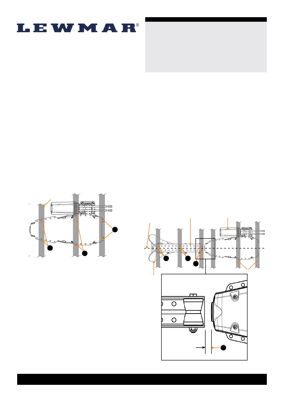
3. Dry t the winch assembly to the beams and mark
its location. The aft most mounting holes on the winch
must align with a beam (Fig. 5A) and at least two pairs of
symmetrical, left and right holes near the middle (Fig. 5B)
and fore (Fig. 5C) of the winch must also align with a
beam. If the beams do not line up with the pre-drilled
mounting holes of the winch a mounting plate is required
for installation. Follow the instructions in the “Installing
the Winch and Bow Roller to Decking or a Mounting
Plate” section in this manual for guided installation.
NOTE: If in doubt about the suitable construction of a
mounting location consult a qualified marine engineer.
The aluminum beams are an integral component of the
winch’s mounting; they must secure the winch and be
strong enough to cope with the high stresses involved in
recovering the anchor.
Bow roller
Anchor
Beams
WinchCenter
Line
4. Dry t the bow roller to the beams noting the marked
location of the winch. The bow roller should be installed
forward of the winch with the aft end of the bow roller
spaced a maximum of 2.54cm (1”) from the fore end of
the winch (Fig. 6A). A larger gap will cause the chain and
warp to become slack and snag. The aft most mounting
holes (Fig. 6B) and fore most holes (Fig. 6D) on the bow
roller must align with a beam (Fig. 6B). Optionally, for
extra security a set of third holes can be aligned near
the center of the bow roller where a beam is available
(Fig. 6C). The winch and bow roller assemblies must be
in line and parallel with each other. Make sure the center
line of the anchor shank or bow roller aligns with the
center line of the winch housing and bow roller (Fig. 6). If
the beams do not line up with the pre-drilled mounting
holes of the bow roller, the winch and bow roller can
not be placed close enough together, or the assemblies
can not be placed parallel and centered in relation to
each other a mounting plate is required. Follow the
instructions in the “Installing the Winch and Bow Roller to
Decking or a Mounting Plate” section in this manual for
guided installation.
Max 2.54cm
(1”)
B
C
A
Beams
Fig.5
D
A
C
B
Fig.6