9
lippert.com 432-LIPPERT (432-547-7378) Rev: 10.20.23
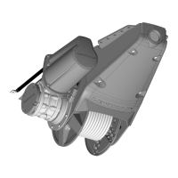
Venta
TM
Pontoon
Anchor Winch
Installation and Owner’s Manual
(For Aftermarket Applications)
CCD-0007416
Wiring
COMPLY WITH ALL LOCAL WIRING AND
ELECTRICAL SAFETY REGULATIONS. WHEN
UNSURE, ALWAYS SEEK GUIDANCE FROM A
QUALIFIED MARINE ELECTRICIAN.
DO NOT CONFUSE CABLE LENGTH WITH THE
LENGTH OF THE VESSEL.
Electric Cable Selection
Cable connecting the winch control box to the power
supply must be customer supplied. Note the total cable
length needed ((Fig. 10A) plus (Fig. 10B) in wiring diagram)
prior to choosing cable and refer to the Appropriate
Cable Gauge/Size by Cable Length table to determine
the gauge of wire needed. Longer runs will require cable
with a smaller gauge.
NOTE: Winch performance is directly related to cable
size and length. Voltage drop over the complete wiring
run must not exceed 10%.
Up to 14 m Up to 40 ft 15-24 m 41-66 ft
16mm^2 4 AWG 25mm^2 2 AWG
General Wiring
The winch must be connected to a suitable 12V DC
power supply.
The power source must be suitably sized for the
expected duration of winch use.
The wiring system should be fully insulated to avoid
possible electrolytic corrosion. It is recommended to use
type III stranded, tinned copper wire with copper crimp
terminals. Most modern installations are negative return
(negative ground) but polarity should be checked.
The winch is supplied with a 5m (16’) harness to allow
through-deck connection to the control box. The
control box should be installed in an enclosed, dry area
above deck.
Circuit Protection
The winch is supplied with a circuit breaker for overload
protection. This must be installed between the power
source (battery) and the winch control box on the positive
cable. The button on the breaker will pop out when an
overload occurs. Depress the button to reset the breaker.
It may need time to cool to allow reset. Do not hold
button in to attempt to override.
Installation MUST use the supplied circuit breaker
to protect the wiring between the power source and
the winch control box. Refer to local standards for
exceptions and restrictions.
DO NOT remove circuit breaker from unit or
otherwise bypass.
Disconnect Isolator
The installation requires a customer-supplied power
disconnect isolator switch between the power source
(battery) and the provided circuit breaker. The isolator
switch should be appropriately sized to safely handle
both the current draw at maximum pull and the
momentary current draw in a stall condition.
The isolator is to be used to switch off the winch system
for safety when it is not in use.
See the Power Specifications table in this manual for
assistance in determining a proper isolator.
Appropriate Cable Gauge/Size by Cable Length
Motor
Supply
Motor
Power
Zero-Load Current
Draw
Current Draw While
Hoisting Tackle
Current Draw While
at Maximum Pull
Maximum Draw in
Stall Condition
12 Volts 850 Watts 40A 65A 100A 447A
Power Specifications
ALL ELECTRICAL WIRING HARNESSES SHALL BE LOOMED AND SECURED TO PREVENT POSSIBLE
DAMAGE AND INSTALLED IN ACCORDANCE WITH ABYC (AMERICAN BOAT AND YACHT COUNCIL)
ELECTRICAL STANDARDS E11 AND S31.