Installation
Relay outputs
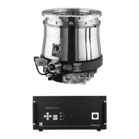
The MAG.DRIVE 2000 converter has 9 relay outputs.
They have changeover contact. Five relay outputs are
permanently assigned a signal.
Failure
Normal operation
Warning
Acceleration
Deceleration
The option relays can output one of the following signals:
Threshold bearing temperature reached
Threshold motor current reached
Threshold frequency reached
No cooling water
No purge gas
1)
TMS temperature OK
Vent
1)
Start command applied
Power supply O.K.
Pump standstill
Option relay 6 can store the selected signal. The option
relays 7, 8, and 9 cannot store the selected signal per-
manently and change to the default setting after a power
interruption. We recommend using only the default set-
tings for the option relays 7, 8, and 9.
Option relay 7 Start command applied
Option relay 8 Power supply O.K.
Option relay 9 Pump standstill
The selection of signals for the option relay and the
adjustment of their thresholds can be achieved via the
operator control menu; see Section 4.3.2.
Analog output
The converter has an analog output which provides an
analog signal (0..10 V) with a 10-bit resolution. The ana-
log output function can be alternatively used to output
motor current
actual frequency
motor temperature
rotor displacement signals (PW24, PV13, PZ12)
The output value can be increased or reduced by a scale
factor; see Section 4.3.2 Settings Converter.
—————
1) not active at MAG W 2010 CHT
28
GA 05.139/1.02 - 06/99
Fig. 26 Assignment control plug X14
X14 50 pole Sub-D I/O
PIN SIGNAL
1 Relay 1 n.o. FAILURE
2 Relay 2 n.o. NORMAL
OPERATION
3 Relay 3 n.o. WARNING
4 Relay 4 n.o. ACCELERATION
5 Relay 5 n.o. DECELERATION
6 Relay 6 n.o. OPTION
7 Relay 7 n.o. OPTION
8 Relay 8 n.o. OPTION
9 Relay 9 n.o. OPTION
10 GND
11 Dig. input REMOTE/LOCAL
12 Dig. input START/STOP
13 Dig. input TMS OFF
14 Dig. input PURGE GAS OFF
1)
15
16 Analog input 1
17 Analog input 2
18 Relay 1 com. FAILURE
19 Relay 2 com. NORMAL
OPERATION
20 Relay 3 com. WARNING
21 Relay 4 com. ACCELERATION
22 Relay 5 com. DECELERATION
23 Relay 6 com. OPTION
24 Relay 7 com. OPTION
25 Relay 8 com. OPTION
26 Relay 9 com. OPTION
27 GND
28 +15V
29 +15V
30 GND
31 GND
32 Analog_GND
33 Analog_GND
34 Relay 1 n.c. FAILURE
35 Relay 2 n.c. NORMAL
OPERATION
36 Relay 3 n.c. WARNING
37 Relay 4 n.c. ACCELERATION
38 Relay 5 n.c. DECELERATION
39 Relay 6 n.c. OPTION
40 Relay 7 n.c. OPTION
41 Relay 8 n.c. OPTION
42 Relay 9 n.c. OPTION
43 GND
44 Dig. input VENTING ON
1)
45 Dig. input Reserve
46 Dig. input Reserve
47 Dig. input EMERGENCY OFF
48 Dig. input EMERGENCY OFF
49
50 Analog output
 Loading...
