Installation
31
GA 05.139/1.02 - 06/99
Analog inputs
The converter has two analog inputs with a 10-bit reso-
lution.
Input signal: 0...10V
A supplementary function can be set for analog input 2
via the operator control menu; see Section 4.3.2:
No function: The input signal can be output via
the serial interface.
Frequency setpoint: In addition to the function descri-
bed above, the drive frequency set-
point is entered via analog input 2.
Digital inputs
The converter has 5 digital inputs with the following
functions:
TMS OFF
Purge gas OFF
1)
Vent ON
1)
The functions are active if a High signal (15 V; e.g. Pins
28 or 29) is connected at the digital input.
Remote
Start (if Remote is active)
The functions Start and Remote are active if a Low sig-
nal (GND; e.g. Pins 27 or 43) is connected at the digital
input.
—————
1) not active at MAG W 2010 CHT
1 +5V Power supply for plug-in control
2 TXD
3 RXD
4 n.c.
5 GND
6 -5V Power supply for plug-in control
7 Reset out for plug-in control
8 select plug-in control input
9 Boot input
Fig. 29 Connector assignment, interface X7
(front side)
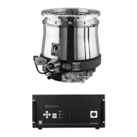
2.8.4 Interface connector
A 9-pin sub-D socket is provided at the front panel. The
connector X7 is assigned the serial interface RS 232. It
is only to be used by the Leybold Service.

 Loading...