Description
10 GA01601_002_C1 - 03/2018 - © Leybold
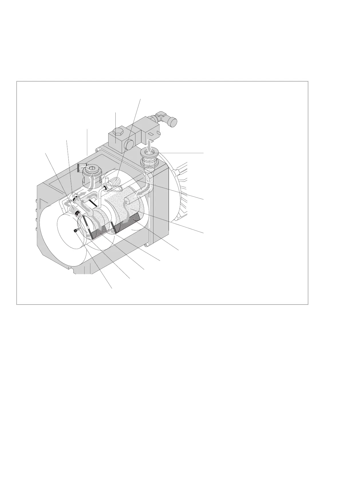
1.1 Function
The rotor (2/5) which is eccentrically arranged in the pump housing (pump
chamber) has two radially slidingvanes (2/6 and 2/8) which divide the pump
chamber ofthe pump into several chambers.
The volume of each chamber changes periodically witheach turn of the rotor
so that the gas at the intake port(2/3) is sucked in. The gas enters the pump
chamber, and after the admission aperture has been sealed off by the vane,
the gas is compressed and moved on.
The compressed gas is ejected from the pump chamberthrough the exhaust
valve. Oil which is entrained in the gas is roughly separated by an internal
demister and at the same time any mechanical contaminations are also
removed from the oil. The gas exits the pump through the exhaust port
(2/13).
Oil injected into the pump chamber serves the purpose of sealing and lubri-
cation. The knocking noise (oil slap) which normally occurs when the pump
approaches its ultimate pressure is avoided by injecting a small amount of air
into the oil so that a silencing effect is attained.
2
3
4
5
6
7
8
9
10
12
13
1
11
1 Gas ballast valve
2 Tandem valve
(vacuum protection)
3 Intake port
4 Oil feed (oil pump)
5 Rotor
6 Vane (HV)
7 High vacuum stage
(pump chamber)
8 Vane (FV)
9 Forevacuum stage
(pump chamber)
10 Non-return valve
11 Exhaust valve
12 Bypass valve
13 Exhaust port
Fig. 2 Principle of operation of the TRIVAC D 2,5 E-LD

 Loading...


