00
Jj
§
()
=
-
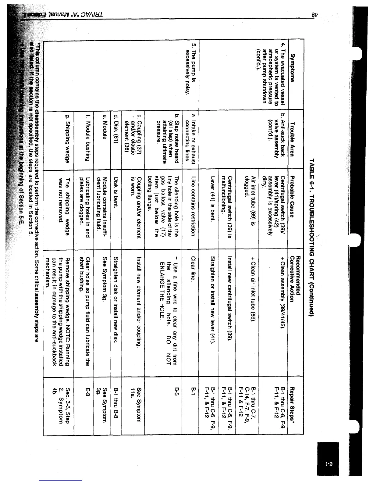
Symptoms
4.
The evacuated vessel
or system is vented to
atmospheric pressure
after pump shutdown
(cont'd.).
5.
The pump is
excessively noisy.
TABLE 6-1. TROUBLESHOOTING CHART (Continued)
Recommended
Trouble
Area
Probable Cause Corrective
Action
b.
Anti-suck back
Centrifugal switch (39)/
+ Clean assembly (39/41142).
valve assembly lever
(41
)/spring
(42)
(cont'd.).
assembly is excessively
dirty.
Air inlet tube
(69)
is
+ Clean air inlet tube
(69).
clogged.
Centrifugal switch
(39)
is
Install new centrifugal switch
(39).
malfunctioning.
Lever
(41)
is bent. Straighten or install new lever
(41).
a.
Intake or exhaust
Line contains restriction
Clear line.
connecting
lines
b.
Slap noise heard
The silencing hole
is
the
+ Use a fine wire to clear any dirt from
(oil slap) when
tiny hole
in
the side of the
the
silencing
hole.
DO
NOT
attaining ultimate
gas ballast valve
(17)
ENLARGE THE HOLE.
pressure.
stem
just
below
the
bolting flange.
c.
Coupling
(37)
Coupling and/or element Install new element and/or coupling.
. and/or elastic
is worn.
element
(36)
d.
Disk
(61)
Disk is bent.
Straighten disk or install new disk.
e.
Module
Module contains insuffi-
See Symptom 3g.
cient lubricating fluid.
f.
Module bushing
Lubricating holes in end
Clear holes
so
pump fluid can lubricate the
plates are clogged.
shaft bushing.
g.
Shipping wedge The shipping wedge Remove shipping wedge. NOTE: Running
was not removed.
the pump with the shipping wedge installed
can result in damage to the anti-suckback
mechanism.
dIsassembly steps required to perform the corrective action. Some critical assembly steps are
specified, the steps are located
in
Section
5.
'tnl",..
ftf
SectIon
6-E.
Repair Steps *
B-1
thru
C-6,
F-9,
F-11, &
F-12
B-1
thru
C-7,
C-14,
F-7, F-9,
F-11&F-12
B-1
thru
C-5,
F-9,
F-11,&F-12
B-1
thru
C-6,
F-9,
F-11,
&
F-12
B-1
B-5
I
See Symptom
11a.
B-1
thru
B-8
See Symptom
3g.
E-3
Sec. 3-3, Step
2.
Symptom
4b.
 Loading...