42
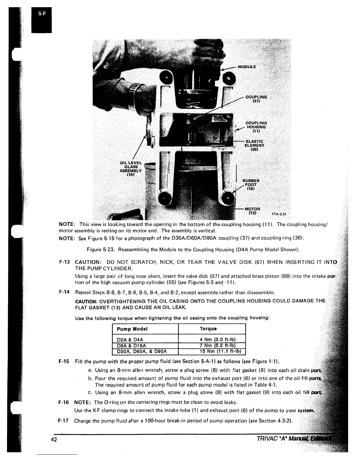
NOTE: This view
is
looking
toward the opening in the
bottom
of
the coupling housing (11). The coupling housing/
motor
assembly
is
resting on its
motor
end. The assembly
is
vertical.
NOTE:
See
Figure 5-15
for
a photograph
of
the
D30A/D60A/D90A
coupling (37) and coupling ring (36).
Figure 5-23. Reassembling the Module
to
the Coupling Housing
(D4A
Pump Model Shown).
F-13
CAUTION:
DO
NOT
SCRATCH, NICK,
OR
TEAR
THE
VALVE
DISK (67) WHEN INSERTING
IT
INTO
THE PUMP
CYLINDER.
Using a large pair
of
long
nose
pliers, insert the
valve
disk (67) and attached
brass
piston (68)
into
the intake por-
tion
of
the high vacuum pump cylinder (55)
(see
Figures
5-3
and
-11).
F-14 Repeat
Steps 8-8, 8-7, 8-6, 8-5, 8-4,
and
8-2, except
assemble
rather than disassemble.
CAUTION: OVERTIGHTENING THE OIL CASING ONTO THE COUPLING HOUSING COULD DAMAGE THE
FLAT
GASKET (13) AND CAUSE AN OIL LEAK.
Use
the
following
torque
when
tightening
the
oil
casing
onto
the
coupling
housing:
Pump
Model
Torque
D2A & D4A
4
Nm
(3.0 ft-Ib)
DBA & D16A
7
Nm
(5.2 ft-Ib)
D30A, D60A,
& D90A
15
Nm
(11.1
ft·lb)
F-15 Fill the pump
with
the proper pump
fluid
(see
Section
5-A-l)
as
follows
(see
Figure
1-11.
a.
Using
an
8-mm allen wrench, screw a plug screw (8)
with
flat
gasket (9)
into
each
oil drain
b. Pour the required amount
of
pump
fluid
into
the exhaust
port
(6)
or
into
one
of
the oil fill
The required amount
of
pump
fluid
for
each
pump model
is
listed in Table 4-1.
c.
Using
an
8-mm allen wrench, screw a plug screw (8)
with
flat
gasket (9)
into
each
oil fiU
F-16 NOTE:
The O-ring on the centering rings must
be
clean
to
avoid leaks.
Use
the
KF
clamp rings
to
connect the intake tube (1)
and
exhaust
port
(6)
of
the
pump
to
your
"v" ..... ;
...
F-17
Change
the
pump
fluid
after a 100-hour break-in period
of
pump operation
(see
Section 4-3-2).
 Loading...


