F-4 Assemble the
gas
ballast valve (20)
as
follows:
a.
For D8A,
D16A,
D30A, D60A,
and
D90A
pump models
only,
reassemble the insides
of
the
cap
end
of
the
gas
ballast valve (17)
as
follows
(see
Figure
5-1
OA).
(1)
Fit
the
a-ring
(20) around the inner rim
of
the valve plate (19). The
a-ring
goes
onto
the side
of
the valve plate
that
has
the metal valve.
(2)
Insert the valve plate
(19)/a-ring
(20) assembly
into
the
top
of
the
gas
ballast valve (17).
The side
of
the valve plate
that
has
the metal valve
faces
down.
(3)
Push
the retaining washer (21)
into
the
top
of
the
gas
ballast valve
until
it
is
tight
against
the valve plate (19).
b.
For
D30A,
D60A,
and
D90A
pump models only, insert the parts
into
the inside
of
the tube end
of
the
gas
ballast valve in the
following
order
(see
Figure 5-10B).
First
Second
Third
Fourth
- Valve plate (32)
that
has
three slots.
-
Spring (31).
- Valve plate (32) washer.
- Retainer ring
(30).
Fit
the retainer ring
into
the groove in the inside
of
the
gas
ballast valve tube.
c.
Repeat Steps
D-l
e through
D-l
a,
except
assemble
rather than disassemble.
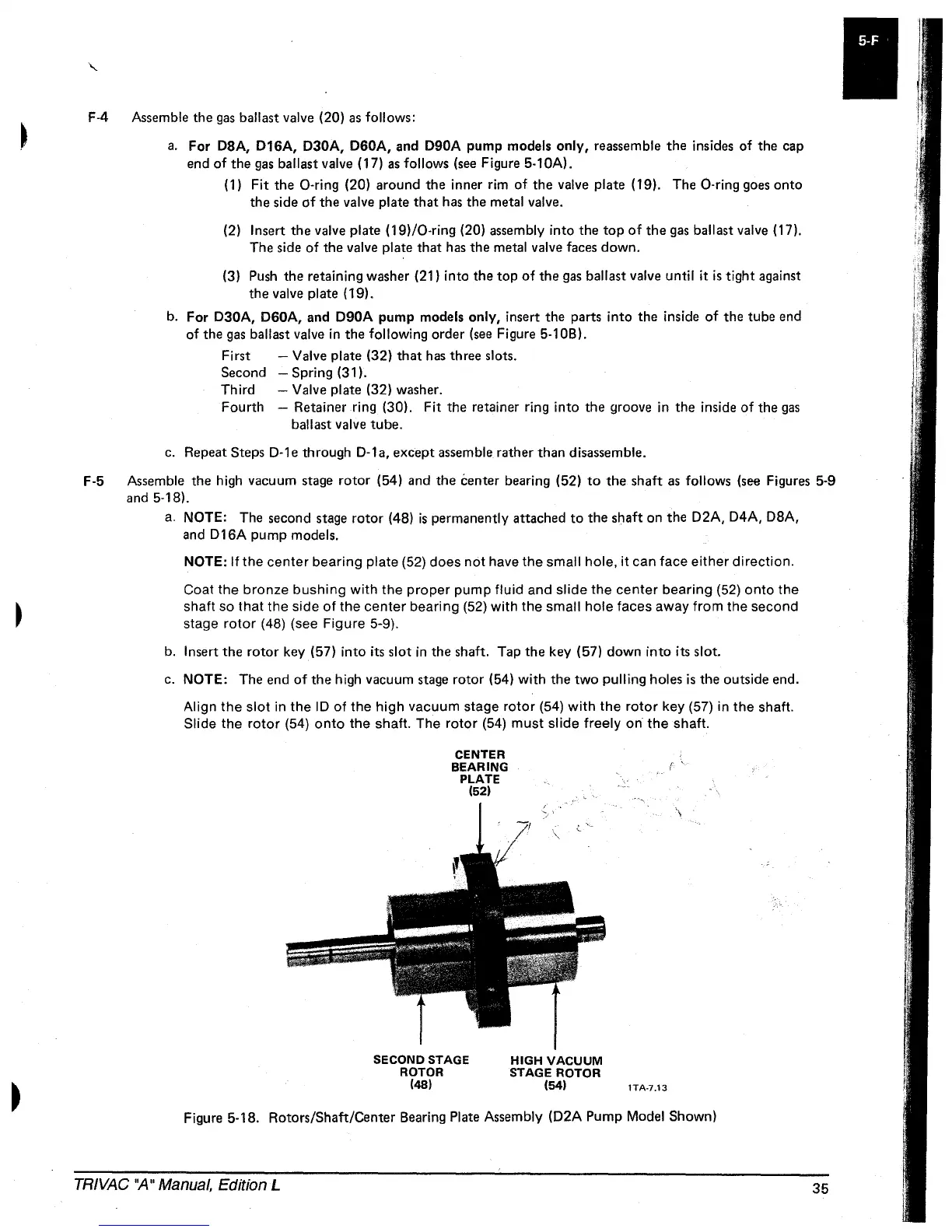
F-5 Assemble the high vacuum
stage
rotor
(54) and the center bearing (52)
to
the shaft
as
follows
(see
Figures 5-9
and
5-181.
a.
NOTE: The second
stage
rotor
(4B)
is
permanently attached
to
the shaft on the
D2A, D4A,
DBA,
and
D16A
pump models.
NOTE:
If
the
center
bearing
plate (52) does
not
have the small hole,
it
can face
either
direction.
Coat
the
bronze
bushing
with
the
proper
pump
fluid
and
slide
the
center
bearing
(52)
onto
the
shaft so
that
the
side
of
the
center
bearing (52)
with
the small
hole
faces away
from
the second
stage
rotor
(48) (see Figure 5-9).
b.
Insert the
rotor
key (57)
into
its slot in the shaft. Tap the key (57)
down
into
its slot.
c.
NOTE:
The end
of
the high vacuum
stage
rotor
(54)
with
the
two
pulling holes
is
the outside end.
Align
the
slot
in
the
ID
of
the
high
vacuum stage
rotor
(54)
with
the
rotor
key (57) in
the
shaft.
Slide the
rotor
(54)
onto
the shaft. The
rotor
(54)
must
slide
freely
on
the
shaft.
CENTER
BEARING
PLATE
(52)
SECOND STAGE
ROTOR
(48)
HIGH
VACUUM
STAGE ROTOR
(54)
r
'.
\
lTA·7.13
Figure
5-1B.
Rotors/Shaft/Center Bearing Plate Assembly
(D2A
Pump Model Shown)
TRIVAC
''A''
Manual, Edition L
35
 Loading...


