97
Electrical System Installation
Due to our policy of continuous product innovation, some specifications may change without notification.
©LG Electronics U.S.A., Inc., Englewood Cliffs, NJ. All rights reserved. “LG” is a registered trademark of LG Corp.
ELECTRICAL
Installing the HMI Indoors
If the power adapter power cord and the HMI power wiring must be installed together, it is necessary to separate the power cable to the HMI from the
communication cable to the HMI to avoid communication problems from electrical interference.
Installing the HMI Indoors
• The HMI can be installed on an interior wall. See below for instructions. Use a drill to add pilot holes
before installing the screws.
• Communication cable for indoor installation is eld-supplied. Communication cable from chiller to HMI is
to be 18 AWG, 2-conductor, twisted, stranded, shielded. Ensure the communication cable shield is properly
grounded to the chiller chassis only. Do not ground the communication cable at any other point.
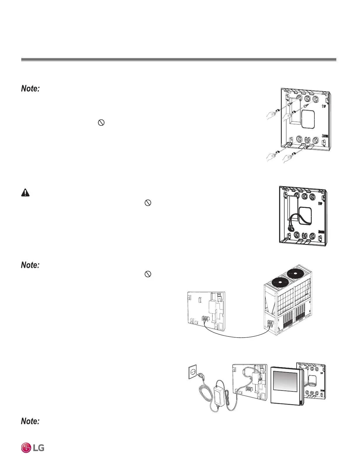
1. Choose the location in which to install the HMI. Verify that it is an appropriate location to connect the
communication cable and power wiring to the HMI, and that its distance from the chiller falls below
maximum wiring / cable length requirements.
2. Use the drier and the M4 screw on the top wall of the communication cable to attach the back panel
of the HMI. See diagram at right. It can be attached as shown, depending on the installation loca-
tion.
3. Pull the communication cable through the hole on the back of the panel.
4. Connect the cable to the communication port located on the back of the HMI.
• Different polarities exist on the communication cable; do not
mix! It will result in a fire, electric shock, and will result in damage
to the compressors and other components.
• To prevent improper connections, mark “A” and “B”, it is recom-
mended to mark A and B on the communication cable. Failure to do
so will result in a communication malfunction.
• Use the ring or fork terminals to connect the communication cable
to the control box terminals. See “Control Panel Configuration” for
the location of the HMI control box.
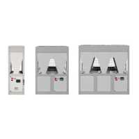
Figure 40: Attaching the Back
Panel of the HMI to the Wall.
Figure 41: Pulling the Communi-
cation Cable Through the Back of
the Panel.
• Different polarities exist on the communication cable; do not mix! It will result in a fire, electric
shock, and will cause physical injury and / or death.
• To prevent improper connections, mark “A” and “B” , it is recommended to mark A and B on the commu-
nication cable. Improper wiring will result in a fire, electric shock, and will cause physical injury and / or
death.
• Use the ring or fork terminals to connect the communication cable to the control box terminals. See
“Control Panel Configuration” for the location of the HMI control box. Improper wiring will result in a
fire, electric shock, and will cause physical injury and / or death.
5. Connect the factory-supplied power adapter to the power terminal
located on the back of the HMI.
6. Assemble the main body of the HMI to the wall panel. Position
the hole at the top of the main HMI unit on the top of the back
panel. Push the bottom of the HMI to the back panel to lock into
place.
7. Plug in the power adapter to the HMI and the power supply.
Figure 42: HMI Terminal.
Figure 43: HMI Terminal.