98
Due to our policy of continuous product innovation, some specifications may change without notification.
©LG Electronics U.S.A., Inc., Englewood Cliffs, NJ. All rights reserved. “LG” is a registered trademark of LG Corp.
LG Air-Cooled Cooling Only Inverter Scroll Chiller Installation and Owners Manual
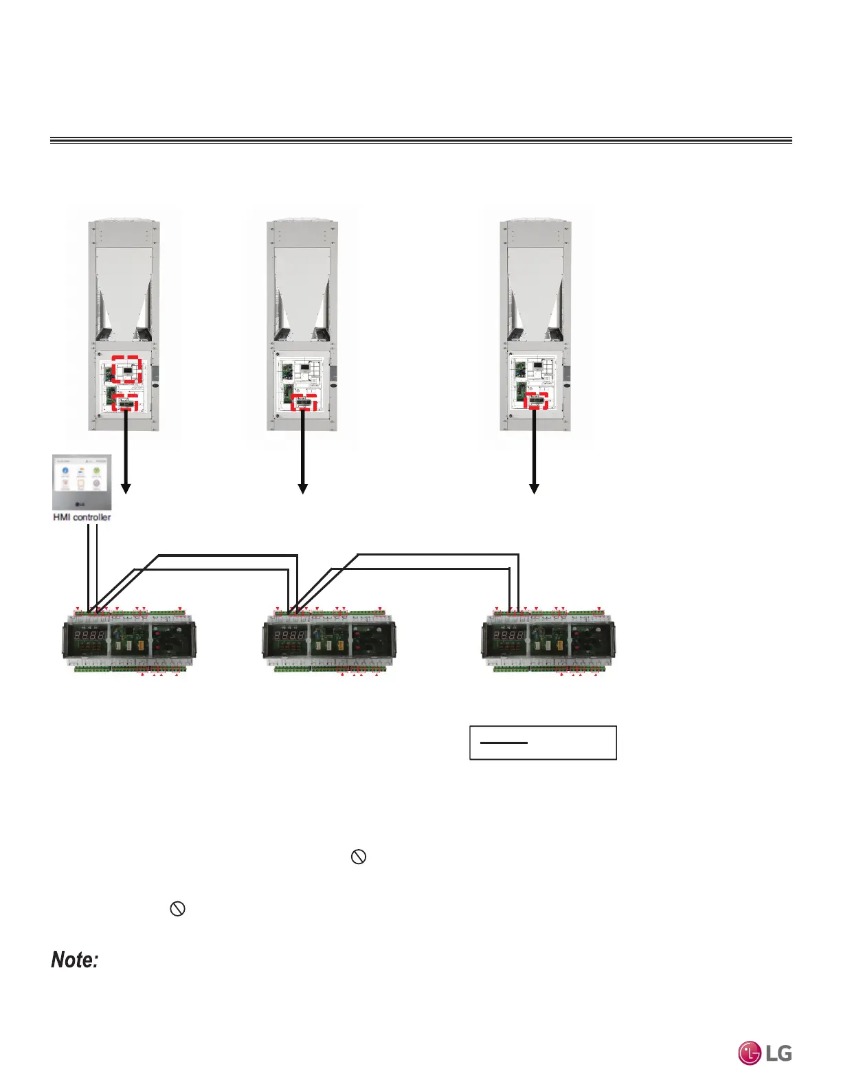
: Field wiring
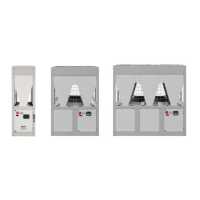
Main Unit Sub A Unit Sub B Unit
Main Controller Main Controller
Main Controller
CH3
3HC3HC
A B
A B
A B
A B
ELECTRICAL
Unit Combination Setup
1. Communication cable is daisy chained from the Main Chiller Main Controller on CH3 to the Sub Chiller(s) Main Controller(s) on CH3
Always Match A to A, and B to B.
2. Communication cable is connected from the HMI Controller to the Main Controller. Always Match A to A, and B to B.
3. Communication cable from chiller to HMI is to be 18 AWG, 2-conductor, twisted, stranded, shielded. Ensure the communication cable
shield is properly grounded to the chiller chassis only. Do not ground the communication cable at any other point. Wiring must comply
with all applicable local and national codes.
4. Install the communication cable and power wiring separately so that communication cable is not impacted by any electric noise generated
from power wiring. Do not install the power wiring and the communication cables in the same conduit.
5. Up to five (5) chillers can be combined using the A-B CH3 bus.
• If the interlocked chiller number and address are not set from the HMI, a communication error will occur. (Refer to the Control > Freezer
Interlock Control about HMI Address Settings in the Chiller Installation and Operation Manual.)
• If Main Controller address does not match the HMI address, a communication error will occur. (Refer to the Control > Freezer Address
Setting about the Controller Address Settings in the Chiller Installation and Operation Manual.)
Figure 44: Unit Combination Setup.