LGE Internal Use Only
Copyright © 2008 LG Electronics. Inc. All right reserved.
Only for training and service purposes
3. TECHNICAL BRIEF
- 43 -
The RBR1000 IC provides two RF inputs; each input supports one 6-MHz band within the range of 698
to 746 MHz. In the United States, this covers UHF TV channels 52 through 59. Each RBR1000 Rx
path begins with a dedicated, gain-stepped LNA. The LNA outputs, only one is active at a time, are
routed to a shared RF-to-baseband quadrature downconverter. The basebandcircuits include in-phase
(I) and quadrature (Q) lowpass filters with passband and stopband characteristics suitable for the FLO
waveform. Baseband buffers drive the analog signals to the MBD1000 device for further processing.
The LO generation and distribution circuits are integrated into the RBR1000 IC; only a few passive
components are required off-chip to implement the phase-locked loop (PLL) filter. Onchip circuits
include the VCO, PLL functions (reference divider, feedback divider, phase detector, and charge
pump), and the distribution circuits that condition the LO signal for driving the quadrature
downconverter.
Most RBR1000 IC control and status information is communicated via a single-wire serial bus interface
(SSBI) with the MBD1000 IC. This SSBI provides efficient initialization and configuration of the
receiver IC. Two dedicated digital inputs (RF_ON and TCXO_ON) from the MBD device supplements
SSBI control of the RFIC.
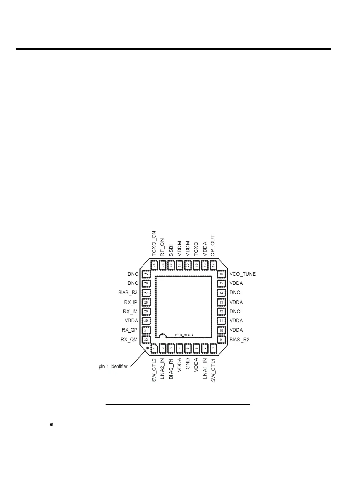
Figure. 3.5.9.1.2 RBR1000 pin assignment (top view)
only CU920