Chapter 4. FUNCTION BLOCKS
4 - 2
4.2 Local Function Block
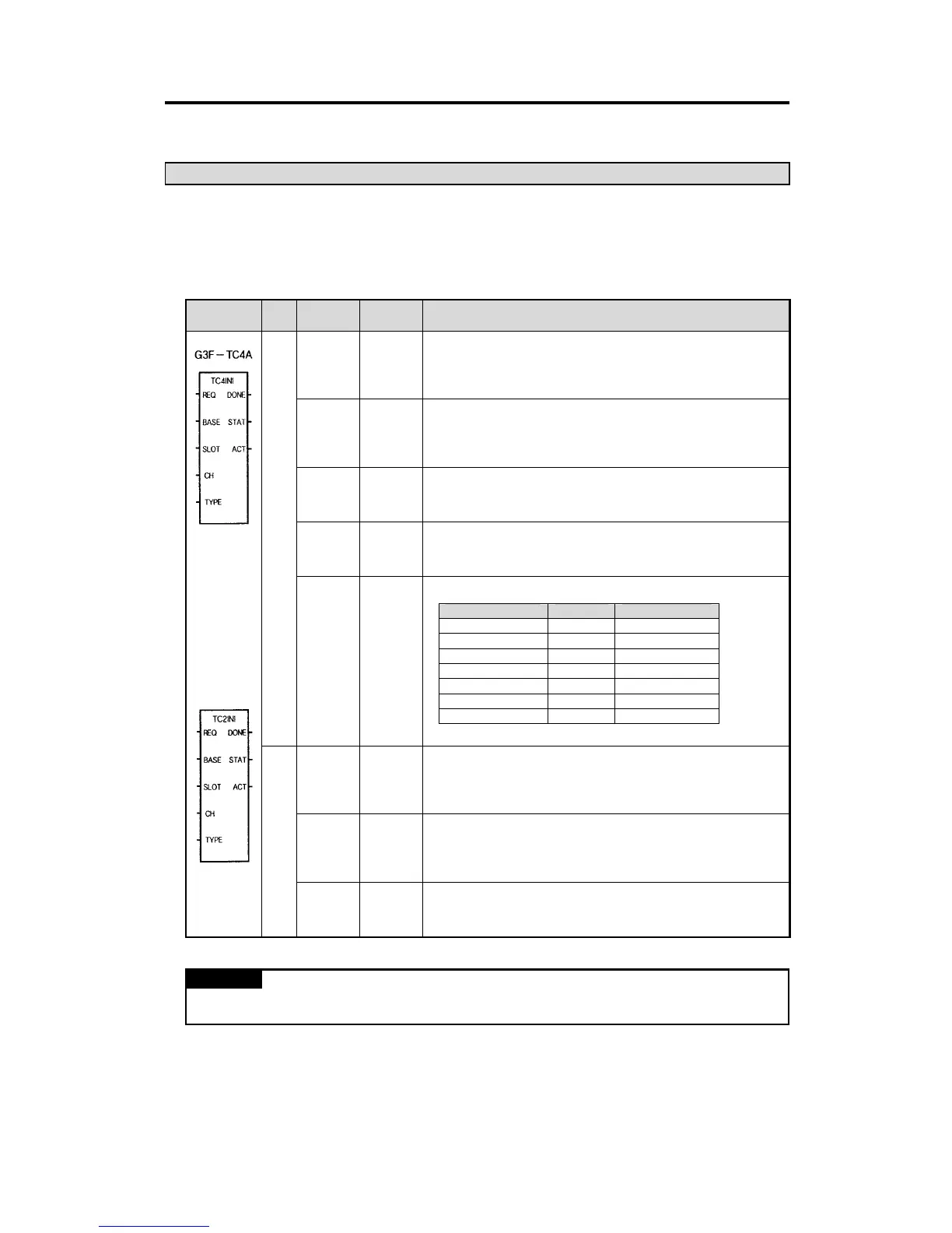
4.2.1 Module Initialization (G3F-TC4A: TC4INI, G4F-TC2A/G6F-TC2A:TC2INI)
Module initialization function block specifies thermocouple input module base location, slot location,
run channel enable/disable and the type of thermocouple for use in program.
Function
Block
I/O Variable
Data
Type
Description
REQ BOOL
Function block execution request area
- Used to request an execution of the initialization function block
- If the conditions connected with this area are established and “0” changes into “1”
while program is running, the initialization function block is executed
BASE USINT
Base location No.
- Used to write the base No. where the thermocouple input module is mounted.
- Setting range: GM1 series(0~31), GM2 series(0~7), GM3/4 series(0-3), GM6
series(0-1)
SLOT USINT
Slot location No.
- Used to write the slot No. where the thermocouple input module is mounted.
- Setting range: 0~7
CH
BOOL
[Array]
*Note 1
Used channel enable/disable specification
- Used to enable or disable a channel for run.
- Specify “1” for enabling, and “0” for disabling
I
TYPE
USINT
[Array]
*Note 1
Specifying the type of the sensor to be connected
- Used to specify the type of sensor connected to each channel.
DONE BOOL
Function block finished execution status
- “1” is output when the initialization function block is finished with no error and
“1” remains until next execution. If an error occur, ‘0’ is displayed and the
operation enters into the stop state.
STAT USINT
Error status indication area
- Used to output the error No. when it occurs during initialization function block
execution.
- For description of errors, refer to the Section 4.4
O
ACT
BOOL
[Array]
*Note 1
Run channel status indication area
- After the initialization function block is finished with no error, “1” is output if the
channel is in normal state. But “0” is output for the disabled channels.
REMARK
∗Note 1 [Array]
: The numbers of Array are 16 in G3F-TC4A, 4 in G4F-TC2A/G6F-TC2A.
Input specification No. Sensor type Temperature range
0 K
-200.0 to 1200.0
°
C
1 J
-200.0 to 800.0
°
C
2 E
-150.0 to 600.0
°
C
3 T
-200.0 to 400.0
°
C
4 B
400.0 to 1800.0
°
C
5 R
0.0 to 1750.0
°
C
6 S
0.0 to 1750.0
°
C
G4F-TC2A/
G6F-TC2A

 Loading...