Chapter 4. FUNCTION BLOCKS
4 - 3
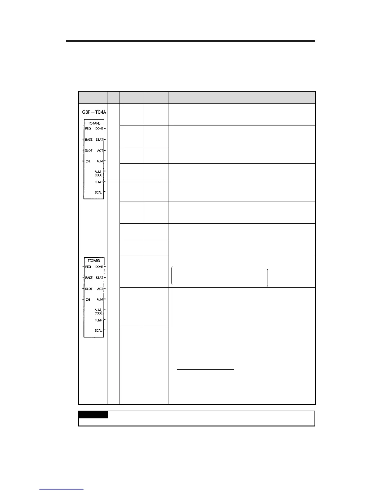
4.2.2 Module Reading (Array type) (G3F-TC4A : TC4ARD, G4F-TC2A/G6F-TC2A : TC2ARD)
The Array type module reading function block executes all channels of the thermocouple input module
in batch processing. If a channel is enabled then the function block outputs the temperature conversion
value to the output value TEMP.
Function
Block
I/O Variable
Data
Type
Description
REQ BOOL
Function block execution request area
- Used to request an execution of the reading function block
- If the conditions connected with this area are established while the program is
running and “0” changes into “1”, the reading function block is executed.
BASE USINT
Base location No.
- Used to write the base No. where the thermocouple input module is mounted.
- Setting range: GM1 series(0~31), GM2 series(0~7), GM3/4 series(0-3), GM6
series(0-1)
SLOT USINT
Slot location No.
- Used to write the slot No. where the thermocouple input module is mounted.
- Setting range: 0~7
I
CH
BOOL
[Array]
*Note 1
Run channel enable/disable specification
- Used to enable or disable a channeI for run.
- Specify “1” for enabling, and “0” for disabling
DONE BOOL
Function block finished execution status
- “1” is output when the reading function block is finished with no error and “1”
remains until next execution. If an error occur, ‘0’ is displayed and the operation
enters into the stop state.
STAT
USINT
Error status indication area
- Used to output the error No. when it occurs during reading function block
execution.
- For description of errors, refer to Section 4.4
ACT
BOOL
[Array]
*Note 1
Run channel status indication area
- After the reading function block is finished with no error, “1” is output if the
channel is in normal state. But “0” is output for the disabled channels.
ALM
BOOL
[Array]
*Note 1
Run channel error indication area
- “1” is outputted when error occurs for each run channel.
ALM_
CODE
USINT
[Array]
*Note 1
Run channel error code area
-Outputs the following code for each channel coded if error occurred.
0: Normal
16: Disconnection detected
17: Out-of-the-measuring-range error
18: Reference junction compensation device error
TEMP
INT
[Array]
*Note 1
Temperature conversion value output area
- The CPU module reads the temperature conversion value of the corresponding
channel from the thermocouple input module and outputs it to this area.
- The temperature conversion value of each channel is 10 times than the real
temperature value.
- (Example: Temperature conversion value 1234
→
Real temperature value
123.4
°
C)
O
SCAL
INT
[Array]
*Note 1
Digital conversion value output area
- The CPU module reads the digital conversion value of the corresponding channel
from the thermocouple input module and outputs it to this area.
- The temperature conversion value of each channel within its measuring
temperature range is converted into a digital value within 0 to 16000 and it is
outputted to this area.
-
The Value read from the output variable SCAL.
- The output value through digital conversion can be used as a PV of the PID
control module.
REMARK
∗Note 1: The numbers of Array are 16 in G3F-TC4A, 4 in G4F-TC2A/G6F-TC2A
.
16000
×
(Temperature conversion value –
Overall measuring Minimum measuring temperature)
temperature range
G4F-TC2A/
G6F-TC2A
 Loading...