Chapter 6. BUFFER MEMORY CONFIGURATION AND FUNCTIONS
6 - 1
Chapter 6. BUFFER MEMORY CONFIGURATION AND FUNCTIONS
The thermocouple-input module has the PLC CPU and the buffer memories for data communications.
6.1 Buffer Memory Configuration
The followings describe buffer memory configuration.
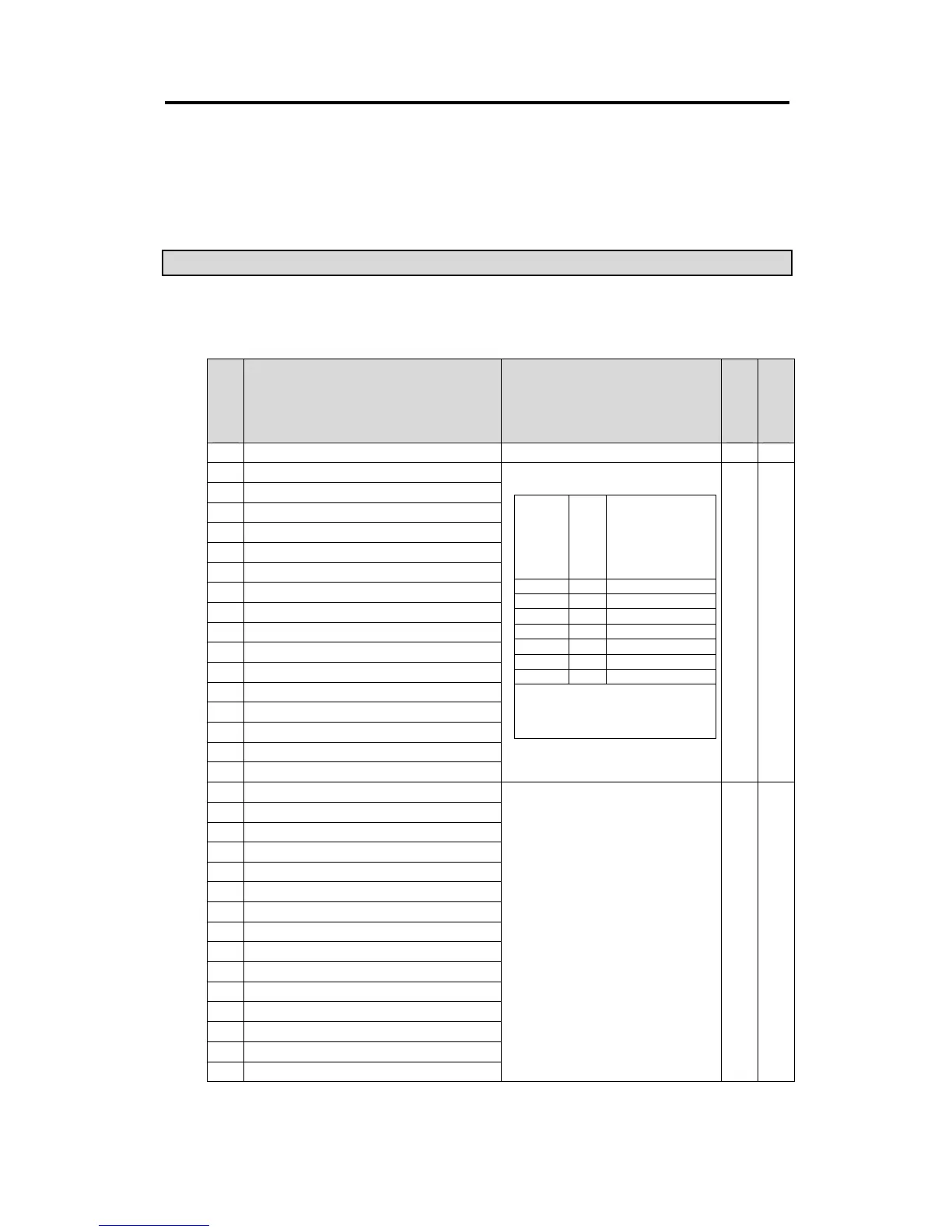
6.1.1 G3F-TC4A Buffer Memory
Address
(Decimal)
Function Description
Default
Setting
Read /
Write
0 Channel enable/disable Specification Bit On(1): Enable, Bit Off(0) : Disable Disable R/W
1 Specifying the type of thermocouple for channel 0
2 Specifying the type of thermocouple for channel 1
3 Specifying the type of thermocouple for channel 2
4 Specifying the type of thermocouple for channel 3
5 Specifying the type of thermocouple for channel 4
6 Specifying the type of thermocouple for channel 5
7 Specifying the type of thermocouple for channel 6
8 Specifying the type of thermocouple for channel 7
9 Specifying the type of thermocouple for channel 8
10 Specifying the type of thermocouple for channel 9
11 Specifying the type of thermocouple for channel 10
12 Specifying the type of thermocouple for channel 11
13 Specifying the type of thermocouple for channel 12
14 Specifying the type of thermocouple for channel 13
15 Specifying the type of thermocouple for channel 14
16 Specifying the type of thermocouple for channel 15
Type K R/W
17 Temperature conversion value of the channel 0
18 Digital conversion value of the channel 0
19 Error code of the channel 0
20 Temperature conversion value of the channel 1
21 Digital conversion value of the channel 1
22 Error code of the channel 1
23 Temperature conversion value of the channel 2
24 Digital conversion value of the channel 2
25 Error code of the channel 2
26 Temperature conversion value of the channel 3
27 Digital conversion value of the channel 3
28 Error code of the channel 3
29 Temperature conversion value of the channel 4
30 Digital conversion value of the channel 4
31 Error code of the channel 4
•
Temperature conversion value
: 10 times of a real temperature is displayed.
•
Digital conversion value
▶
If a temperature conversion value is converted
into a value within 0 to 16000, that value is a
digital conversion value.
▶
It can be used as a process value of the PID
control module.
▶
Expression
Digital conversion value = (16000/
measuring temperature range)
×
(temperature conversion value –
minimum measuring temperature)
•
Error code
16 : Disconnection detection error
17 : Upper or lower overflow
18 : Reference junction compensation device
error
Read
Only
Input
specification
No.
Sensor type
Temperature
range
0 K
-200.0 to 1200.0
°
C
1 J
-200.0 to 800.0
°
C
2 E
-150.0 to 600.0
°
C
3 T
-200.0 to 400.0
°
C
4 B
400.0 to 1800.0
°
C
5 R
0.0 to 1750.0
°
C
6 S
0.0 to 1750.0
°
C
If a value outside the defined range is set,
the bit of address 67 that corresponds to
the channel turns on and the thermocouple
type will be set to type K.
 Loading...