Copyright © 2008 LG Electronics. Inc. All right reserved.
Only for training and service purposes
LGE Internal Use Only
2-37
Pin Name I/O Description Option
Port 7 • 4-bit I/O port
• I/O specifiable in 1-bit units
• Pull-up resistor can be turned on and off in 1-bit units
• Shared pins
P70 : INT0 input/HOLD reset input/timer 0L capture input/watchdog timer output
P71 : INT1 input/HOLD reset input/timer 0H capture input
P72 : INT2 input/HOLD reset input/timer 0 event input/timer 0L capture input/
high speed clock counter input
P73 : INT3 input (with noise filter)/timer 0 event input/timer 0H capture input
AD converter input port: AN8 (P70), AN9 (P71)
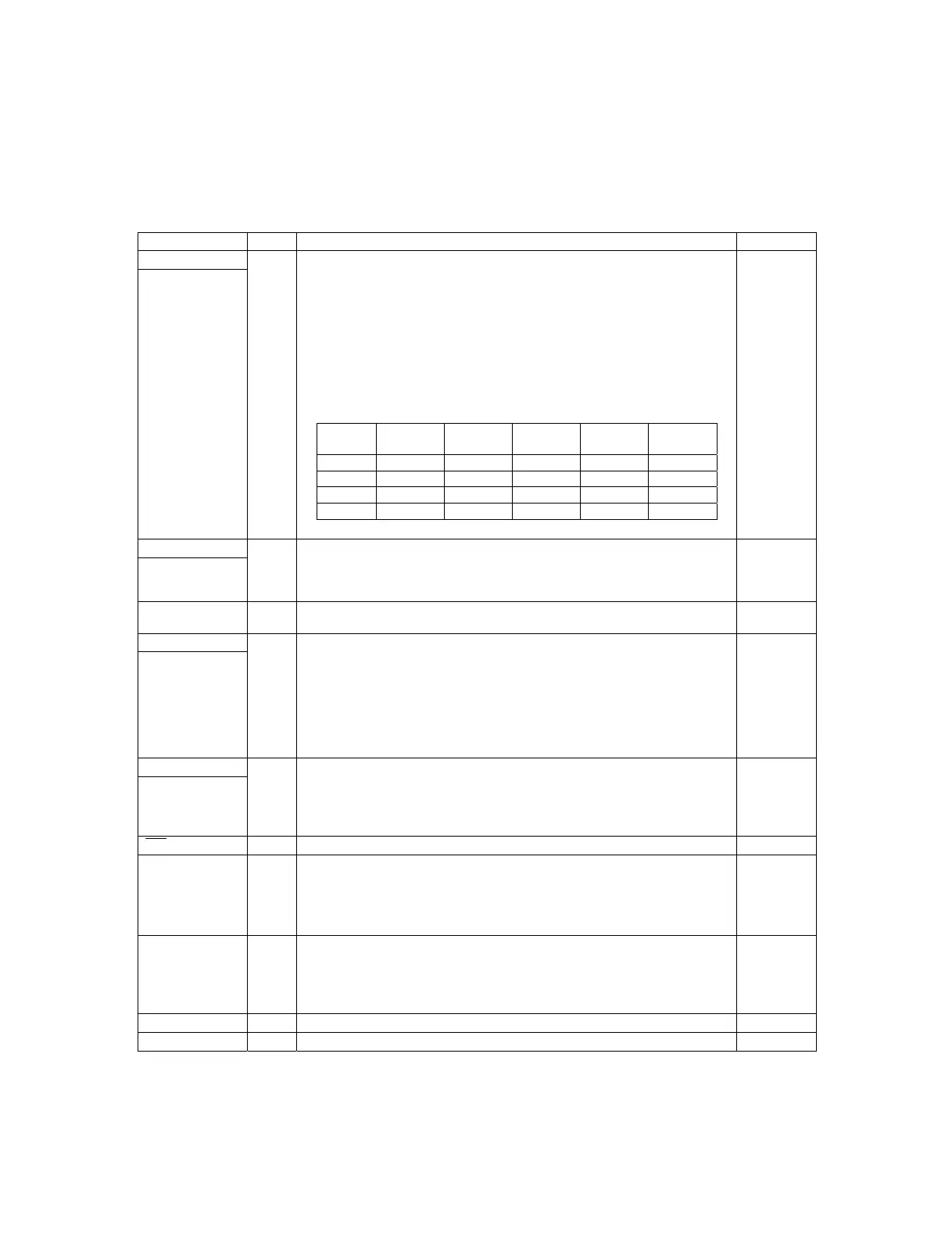
• Interrupt acknowledge ty
pe
Rising Falling
Rising/
Falling
H level L lev
el
INT0 enable enable disable enable
enable
INT1 enable enable disable enable
enable
INT2 enable enable enable disable
disable
INT3 enable enable enable disable
disable
P70 to P73
I/O
No
Port 8
P80 to P86
I/O • 7-bit I/O port
• I/O specifiable in 1-bit units
• Shared pins
AD converter input port : AN0 (P80) to AN6 (P86)
No
PWM2
PWM3
I/O • PWM2 and PWM3 output ports
• General-purpose I/O available
No
Port 3
P30 to P37
I/O • 8-bit I/O port
• I/O specifiable in 1-bit units
• Pull-up resistor can be turned on and off in 1-bit units
• Pin functions
P32: UART1 transmit
P33: UART1 receive
P34: UART2 transmit
P35: UART2 receive
Ye
s
Port C
PC0 to PC7
I/O • 8-bit I/O port
• I/O specifiable in 1-bit units
• Pull-up resistor can be turned on and off in 1-bit units
• Pin functions
PC5 to PC7: On-chip Debugger
Ye
s
RES
Input Reset pin
No
XT1 Input • 32.768kHz crystal oscillator input pin
• Shared pins
General-purpose input port
AD converter input port : AN10
Must be connected to V
DD
1 if not to be used.
No
XT2 I/O • 32.768kHz crystal oscillator output pin
• Shared pins
General-purpose I/O port
AD converter input port : AN11
Must be set for oscillation and kept open if not to be used.
No
CF1 Input Ceramic resonator input pin
No
CF2 Output Ceramic resonator output pin
No