108
MULTI V IV System Installation Manual
Due to our policy of continuous product innovation, some specications may change without notication.
©LG Electronics U.S.A., Inc., Englewood Cliffs, NJ. All rights reserved. “LG” is a registered trademark of LG Corp.
Pipe Sizing for Heat Pump Systems
REFRIGERANT PIPING DESIGN
The following is an example of manual pipe size calculations. Designers are highly encouraged to use LATS instead of manual calculations.
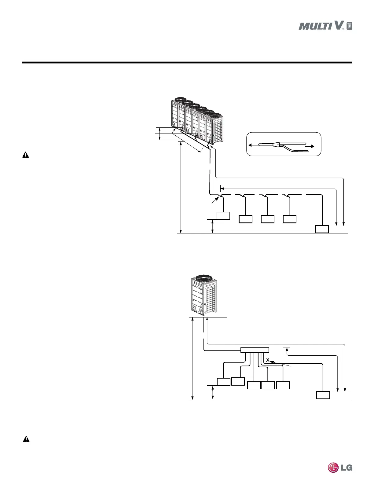
Y-branch Pipe Sizing When Installing a Triple-Frame System
Example: Five (5) indoor units connected
ODU: Outdoor Units.
IDU: Indoor Units.
A: Main Pipe from Outdoor Unit to Y-branch.
B: Y-branch to Y-branch.
C: Y-branch to Indoor Unit.
Header Pipe Sizing When Installing a Single Outdoor Unit System
Example: Six (6) indoor units connected
ODU: Outdoor Units
IDU: Indoor Units
A: Main Pipe from Outdoor Unit to Header
C: Header to Indoor Unit
• Larger-capacity outdoor units must be the
master in a multi-frame system.
• Single-compressor outdoor units (72,000 Btu/h
capacity) cannot be the master outdoor unit in
a multi-frame system.
• Master outdoor unit capacity must be greater
than or equal to the slave1 outdoor unit capac-
ity, and, where applicable, slave1 outdoor unit
capacity must be greater than or equal to the
slave2 outdoor unit capacity.
height1 ≤16-7/16 feet
≤33 feet
Slave1 ODU
Slave2 ODU
Master ODU
Y-branch
To indoor units
To
outdoor
units
A
C CC C
C
B
B
B
Elevation1: ≤361 feet
Elevation2: ≤131 feet
Length: ≤492 feet (656 feet conditional application)
ℓ:
≤131 feet (295 feet conditional application)
IDU
IDU
IDU
IDU
Y-branch
IDU
A
C
C
C
C
C
C
ℓ:
≤131 feet (295 feet
conditional application)
Length: ≤492 feet (656 feet conditional application)
Elevation2: ≤131 feet
Brazed Cap
Header
IDU
IDU
IDU
IDU IDU
IDU
See pages 109-110 for refrigerant pipe diameter and pipe length tables.
 Loading...

