114
MULTI V IV System Installation Manual
Due to our policy of continuous product innovation, some specications may change without notication.
©LG Electronics U.S.A., Inc., Englewood Cliffs, NJ. All rights reserved. “LG” is a registered trademark of LG Corp.
The following is an example of manual pipe size calculations. Designers are highly encouraged to use LATS instead of manual calculations.
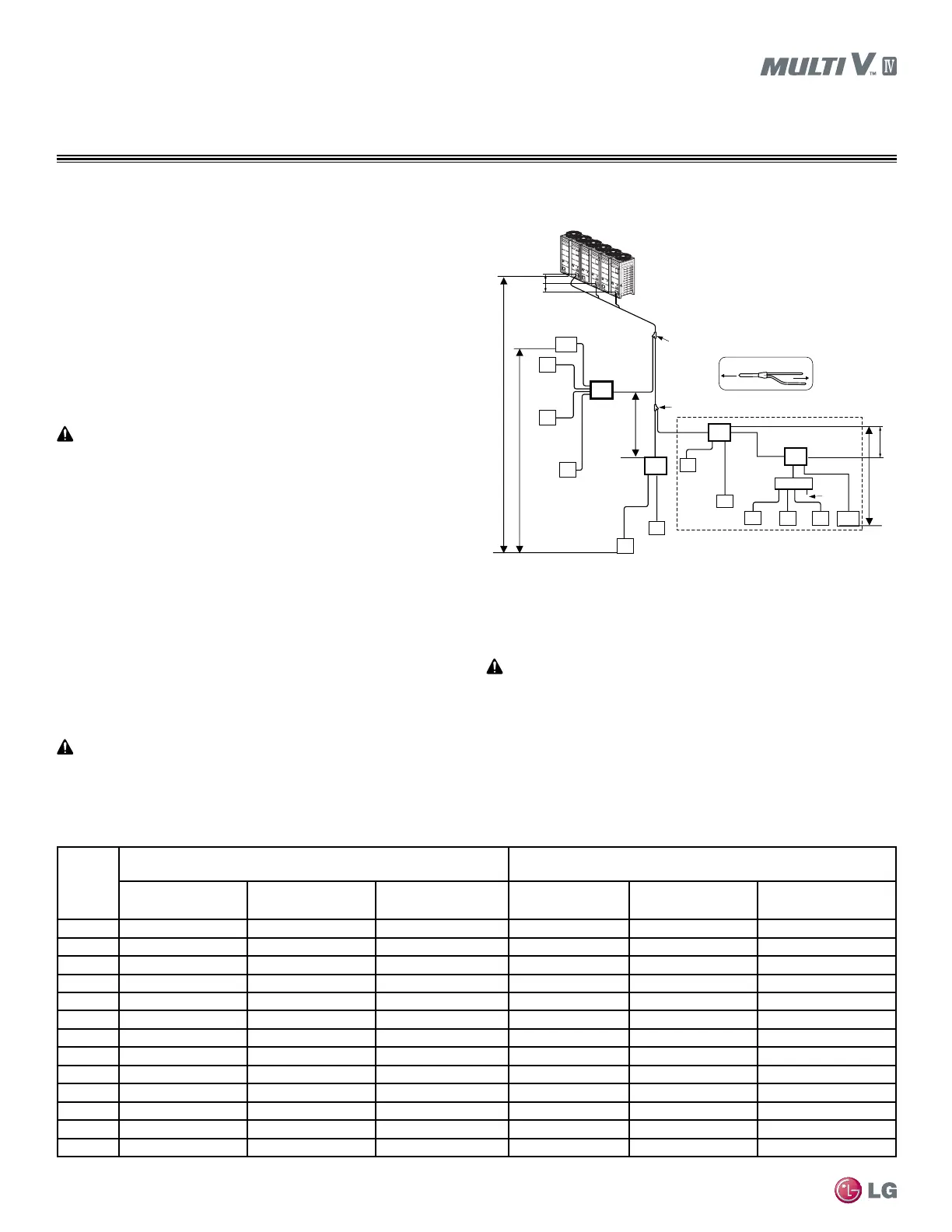
REFRIGERANT PIPING DESIGN
Pipe Sizing for Heat Recovery Systems
Example: Triple-frame system, four (4) heat recovery units,
one (1) header, and twelve (12) indoor units connected
ODU:OutdoorUnits.
HRU:HeatRecoveryUnits.
IDU:Indoorunits.
A:MainPipefromOutdoorUnittoFirstY-branch.
B:HeatRecoveryUnittoHeatRecoveryUnit,Y-branchtoHeat
RecoveryUnit,HeatRecoveryUnittoHeader,orY-branchtoY-branch.
C:HeatRecoveryUnit/HeadertoIndoorUnit.
Pipe Sizing When Installing Heat Recovery Units
•Connection piping from branch to branch cannot exceed the main
pipe diameter (A) used by the outdoor unit.
•Install the header branches or heat recovery units so that the pipe
distances between the connected indoor units are minimized. Large
differences in pipe distances can cause indoor unit performances to
uctuate.
•Y-branches and other headers branches cannot be installed down-
stream of the initial header branch.
•Indoor units must be installed at a position lower than the header.
•Total capacity of indoor units in series connection of heat recovery
units≤192,400Btu/h.
•If large capacity indoor units (>12,000 Btu/h with piping sizes
>5/8Ø/3/8Ø)areinstalled,thevalvegroupsettingshouldbeused.
(Refer to the PCB of the heat recovery unit for the valve group
control setting.)
•Always reference the LATS Multi V software report.
•Larger-capacity outdoor units must be the master in a multi-frame
system.
•Single-compressoroutdoorunits(72,000Btu/hcapacity)cannotbethe
master outdoor unit in a multi-frame system.
•Master outdoor unit capacity must be greater than or equal to the slave1
outdoorunitcapacity,and,whereapplicable,slave1outdoorunitcapac-
itymustbegreaterthanorequaltotheslave2outdoorunitcapacity.
See pages 114-115 for refrigerant pipe diameter and pipe length
tables.
ODU
Capacity
(ton)
Standard Pipe Diameter
Pipe diameter when pipe length is ≥295 feet or when height
differential (ODU ↔IDU) is >164 feet
Liquid Pipe
(inches OD)
Low Pressure Vapor
Pipe (inches OD)
High Pressure Vapor
Pipe (inches OD)
Liquid Pipe
(inches OD)
Low Pressure Vapor
Pipe (inches OD)
High Pressure Vapor
Pipe (inches OD)
6 3/8Ø 3/4Ø 5/8Ø 1/2Ø 3/4Ø 5/8Ø
8 3/8Ø 7/8Ø 3/4Ø 1/2Ø 7/8Ø 3/4Ø
10 1/2Ø 1-1/8Ø 3/4Ø 5/8Ø 1-1/8Ø 3/4Ø
12 1/2Ø 1-1/8Ø 7/8Ø 5/8Ø 1-1/8Ø 7/8Ø
14 5/8Ø 1-1/8Ø 7/8Ø 3/4Ø 1-1/8Ø 7/8Ø
16 5/8Ø 1-1/8Ø 7/8Ø 3/4Ø 1-1/8Ø 7/8Ø
18 5/8Ø 1-3/8Ø 1-1/8Ø 3/4Ø 1-3/8Ø 1-1/8Ø
20 5/8Ø 1-3/8Ø 1-1/8Ø 3/4Ø 1-3/8Ø 1-1/8Ø
22 3/4Ø 1-3/8Ø 1-1/8Ø 7/8Ø 1-3/8Ø 1-1/8Ø
24 3/4Ø 1-3/8Ø 1-1/8Ø 7/8Ø 1-3/8Ø 1-1/8Ø
26 3/4Ø 1-3/8Ø 1-1/8Ø 7/8Ø 1-3/8Ø 1-1/8Ø
28 3/4Ø 1-3/8Ø 1-1/8Ø 7/8Ø 1-3/8Ø 1-1/8Ø
30 3/4Ø 1-5/8Ø 1-1/8Ø 7/8Ø 1-5/8Ø 1-1/8Ø
Table40:MainPipe(A)DiameterfromOutdoorUnittoFirstY-branch.
Case 1: Maximum height is 131 feet if installed with a Y-branch.
Case 2: Maximum height is 16 feet in heat recovery control unit series connection.
*
Elevation1
Elevation2
Master ODU
Slave1
ODU
ODU
Case 1
Case 2
A
Y-branch (first)
B
C
Closest
IDU
C
HRU
C
C
B
B
C
C
C
C
B
B
C
C
x
Header
C
C
To indoor units
To
outdoor unit
Y-branch
height1
≤16-7/16 feet
B
Y-branch (second)
HRU
HRU
HRU
IDU
IDU
IDU
IDU
IDU
IDU
IDU
IDU
IDU
IDU
Farthest
IDU
Brazed
cap
49 feet
16 feet
Elevation3
 Loading...

