115
Installation
Due to our policy of continuous product innovation, some specications may change without notication.
©LG Electronics U.S.A., Inc., Englewood Cliffs, NJ. All rights reserved. “LG” is a registered trademark of LG Corp.
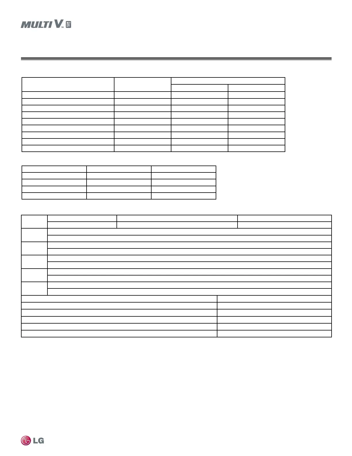
REFRIGERANT PIPING DESIGN
Pipe Sizing for Heat Recovery Systems
Downstream IDU total capacity (Btu/h) Liquid pipe (inches OD)
Vapor pipe (inches OD)
Low pressure High pressure
≤19,100 1/4Ø 1/2Ø 3/8Ø
<54,600 3/8Ø 5/8Ø 1/2Ø
<76,400 3/8Ø 3/4Ø 5/8Ø
<114,700 3/8Ø 7/8Ø 3/4Ø
<172,000 1/2Ø 1-1/8Ø 7/8Ø
<229,400 5/8Ø 1-1/8Ø 7/8Ø
<248.500 5/8Ø 1-3/8Ø 1-1/8Ø
<344,000 3/4Ø 1-3/8Ø 1-1/8Ø
<592,500 3/4Ø 1-5/8Ø 1-3/8Ø
Length
Totalpipelength Longestactualpipelength Equivalentpipelength
1
A+ΣB+ΣC≤3,280feet ≤492feet(656feetconditionalapplication) ≤574feet(738feetconditionalapplication)
ℓ
Longestpipelengthafterfirstbranch
≤131feet(295feetconditionalapplication)
Elevation1
Elevationdifferential(OutdoorUnit↔IndoorUnit)
Height≤361feet
Elevation2
Elevationdifferential(IndoorUnit↔IndoorUnitconnectedtoparallelheatrecoveryunits)
height≤131feet
Elevation3
Elevationdifferential(IndoorUnittoHeatRecoveryUnit[singleHeatRecoveryUnitorseriesHeatRecoveryUnits])
≤49feet
height1
Elevationdifferential(OutdoorUnit↔OutdoorUnit)
≤16.4feet
Distance between Outdoor Unit to Outdoor Unit ≤33feet(Max.43feetforOutdoorUnit≥12tons)
Distance between ttings and Indoor Unit ≥20inches
Distance between ttings and Y-branches / Headers ≥20inches
Distance between two Y-branches / Headers ≥20inches
Height differential between two Heat Recovery Units if installed with a Y-branch ≤49feet
Height differential between two series-piped Heat Recovery Units ≤16feet
Table41:RefrigerantPipe(B)DiameterbetweenY-branchesandY-branches/HeatRecoveryUnit/Headers.
Table42:IndoorUnitConnectingPipefromBranch(C).
1
Forcalculationpurposes,assumeequivalentpipelengthofY-branchestobe1.6feet,andtheequivalentpipelengthofheaderstobe3.3feet.
Conditional Applications
Conditional application is computed in LATS. See below for an explanation of when pipes are upsized.
IftheequivalentlengthbetweenthefirstY-branchtothefarthestindoorunitis>131feet(maximum295feet):
•Pipesegmentdiametersbetweenthefirstbranchandthelastbranchshouldbesizedupbyone.Thisappliestobothliquidandlow/high
vaporpipes.Ifthenextsizeupisnotavailable,orifthepipesegmentdiametersarethesameasmainpipe(A)diameters,sizingupisnot
possible.
•Whilecalculatingtotalrefrigerantpipinglength,pipe(B)segmentlengthsbetweenthefirstY-branchandsecondY-branch,andbetweenthe
secondY-branchandtheheatrecoveryunitshouldbecalculatedbytwo.
•Lengthofpipe(C)fromeachindoorunittotheclosestY-branch,header,orheatrecoveryunit≤49feet.
•[Lengthofpipefromoutdoorunittofarthestindoorunit(A+B+C)]-[Lengthofpipefromoutdoorunittoclosestindoorunit(A+B+C)]≤131
feet.
Table43:PipeCapabilities.
Indoor Unit Capacity
1
Liquid pipe (inches OD) Vapor pipe (inches OD)
≤19,100 1/4Ø 1/2Ø
≤54,600 3/8Ø 5/8Ø
≤76,400 3/8Ø 3/4Ø
≤95,900 3/8Ø 7/8Ø
1
9,600-24,200Btu/h4-way3feetx3feetCassetteand15,400-24,200Btu/hHighStaticDuctedIDUshave3/8Ø(liquid)and5/8Ø(vapor).
The following is an example of manual pipe size calculations. Designers are highly encouraged to use LATS instead of manual calculations.
 Loading...

