120
MULTI V IV System Installation Manual
Due to our policy of continuous product innovation, some specications may change without notication.
©LG Electronics U.S.A., Inc., Englewood Cliffs, NJ. All rights reserved. “LG” is a registered trademark of LG Corp.
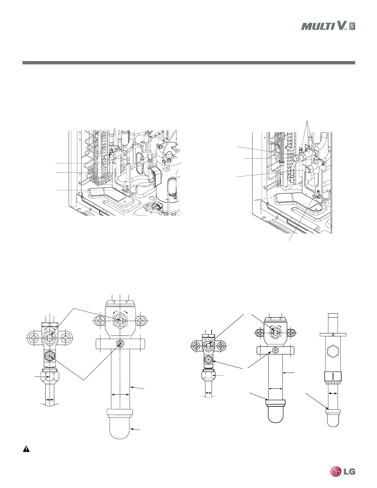
REFRIGERANT PIPING DESIGN
• Connect the end of the pipe to the branch pipes.
• Outdoor unit refrigerant pipes are divided at the end to connect to each indoor unit.
• Use flare connections for the indoor units, and braze connections for the outdoor pipes and branch pipes.
• Use a hexagon wrench to open and close the valve.
Figure 30: Heat Pump Outdoor Unit Valves.
Figure 31: Heat Recovery
Outdoor Unit Valves.
Pipe Connections and Factory-supplied Shut-off Valve Operation
Vapor pipe
Service Port
Liquid pipe
Refrigerant
Charging Port
Service Port
Liquid pipe
Low Pressure
Vapor pipe
High Pressure
Vapor pipe
Refrigerant Charging Port
1. Field piping.
2. Flare nut.
3. Ball type service valves.
4. Schrader valves.
5. Liquid pipe.
6. Vapor pipe.
7. Field-supplied 90° elbow.
Heat Pump Unit Service / Schrader
Valve Detail
Heat Recovery Unit Service /
Schrader Valve Detail
Vapor Pipe Service Port
Liquid Pipe Service Port
2
5
4
3
1
6
7
Liquid Pipe
Service Valve
Low-pressure Vapor
Pipe Service Valve
High-pressure Vapor
Pipe Service Valve
1
2
5
8
3
6
4
78
1. Field piping.
2. Flare nut.
3. Ball type service valves.
4. Schrader valves.
5. Liquid pipe.
6. Low-pressure Vapor pipe.
7. High-pressure Vapor pipe
8. Field-supplied 90° elbow.
Do not expose the service valves of the outdoor unit to heat. Protect the service valve with a wet towel during brazing.
 Loading...

