98
MULTI V IV System Installation Manual
Due to our policy of continuous product innovation, some specications may change without notication.
©LG Electronics U.S.A., Inc., Englewood Cliffs, NJ. All rights reserved. “LG” is a registered trademark of LG Corp.
LG Engineered Y-branch Kits and Header Kits
LG Y-branch and Header kits are highly engineered devices designed to evenly divide the flow of refrigerant, and are used to join one pipe
segment to two or more segments.
No Substitutions
Only LG supplied Y-branch and Header ttings (as referenced below; sold separately) can be used to join one pipe segment to two or more
segments. Third-party or eld-fabricated Tee’s, Y-ttings, Headers, or other branch ttings are not qualied for use with LG Multi V IV systems.
The only eld-provided ttings allowed in a Multi V IV piping system are 45° and 90° elbows.
Table 29: Y-Branches and Headers.
Y-branches
Headers
4 branch 7 branch 10 branch
ARBLN01621 ARBLN07121 ARBLB01621 ARBLB07121 ARBL054 ARBL057 ARBL1010
ARBLN03321 ARBLN14521 ARBLB03321 ARBLB14521 ARBL104 ARBL107 ARBL2010
LG Y-branch kits consist of:
• Y-branches (liquid line, vapor lines).
• Reducer fittings as applicable.
• Molded clam-shell type insulation covers.
LG Header kits consist of:
• Two Headers (one liquid line, one vapor line).
• Reducer fittings as applicable.
• Molded clam-shell type insulation covers.
• If the diameter of the branch pipe segments differ from that of the designated refrigerant piping, trim the to the desired section using a pipe
cutter, and then use an adapter to connect.
• Always follow manufacturer’s guidelines on refrigerant piping restrictions such as maximum length, elevation difference, and diameters. Fail-
ure to do so can result in reduced heating / cooling performance or equipment malfunction.
Y-Branch Kits
LG supplied Y-branches must be used at each transition. Field-supplied “T” fit-
tings or “Y” branches are not acceptable. Each LG supplied Y-branch kit comes
with two (2) Y-branches for indoor units, step-down pipe reducers, and insulation
covers.
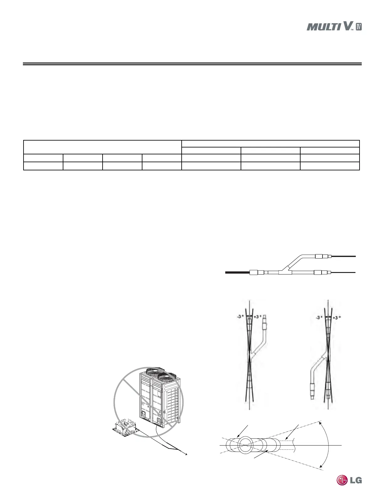
Y-branches may be installed in horizontal or vertical configurations. When in-
stalled vertically, position the Y-branch so the straight-through leg is ±3° of plumb.
When installed horizontally, position the Y-branch so the take-off leg is level and
shares the same horizontal plane as the straight-through leg ±10° rotation.
There is no limitation on the number of Y-branches that can be installed, but there
is a limitation on the number of indoor units connected to a single outdoor unit.
Y-branches should always be installed with the single port facing the outdoor
unit, the two-port end facing indoor units (Do not install Y-branches backwards as
shown in Figure 11.) Refrigerant flow cannot make U-turns through Y-branches.
The first Y-branch kit must be located at least three (3) feet from the outdoor unit.
Figure 8: Y-branch Connections.
Vertical up conguration.
Vertical down conguration.
Figure 9: Y-branch Installation Alignment Specication.
Figure 10: Horizontal Conguration End View.
Figure 11: Diagram of an Incorrect Y-branch
Installation.
REFRIGERANT PIPING DESIGN
System Engineering
±10°
Horizontal Plane
±10°
Branch Leg
Straight-through Leg
Y-branch Inlet
To indoor unit
To indoor unit
To outdoor unit
To
i
n
do
or u
n
i
ts
T
o next
bran
ch
Provide a minimum of 20 inches
between a Y-branch and any
other fittings or indoor unit piped
in series. It is recommended that
when a Y-branch is located in a
pipe chase or other concealed
space, access doors should be
provided for inspection access.
The equivalent pipe length of
each Y-branch (1.6′) must be
added to each pipe segment
entered into LATS piping design
software.
 Loading...

