99
Installation
Due to our policy of continuous product innovation, some specications may change without notication.
©LG Electronics U.S.A., Inc., Englewood Cliffs, NJ. All rights reserved. “LG” is a registered trademark of LG Corp.
REFRIGERANT PIPING DESIGN
System Engineering
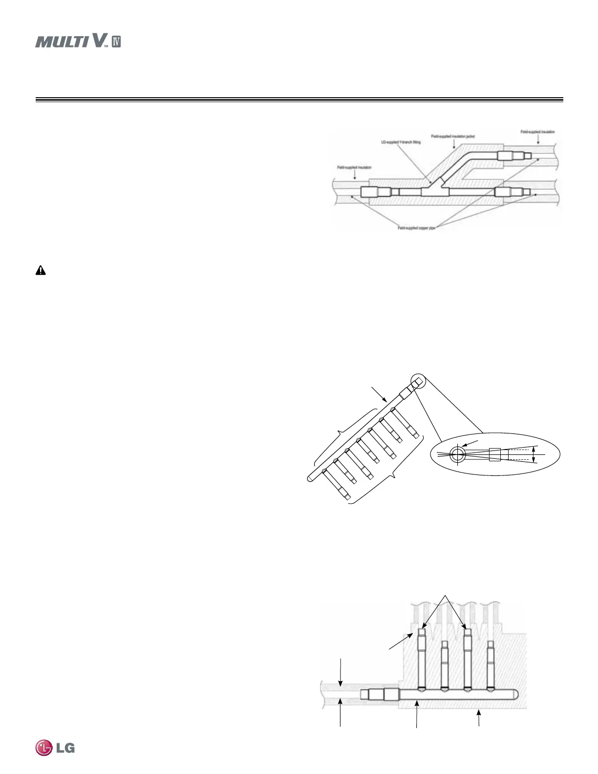
Figure 12: Y-branch Insulation and Pipe Detail.
Install Correctly
• Y-branches can be installed upstream between the Header and the outdoor unit, but a Y-branch cannot be installed between a header
and an indoor unit.
• To avoid the potential of uneven refrigerant distribution through a header fitting, minimize the difference in equivalent pipe length
between the header fitting and each connected indoor unit.
Header kits are intended for use where multiple indoor units are in
the same vicinity and it would be better to “home-run” the run-out
pipes back to a centralized location. If connecting multiple indoor
units that are far apart, Y-branches may be more economical. See
pages 39 or 79 for Header kit specifications and capacities.
Y-branches can be installed between the Header and the outdoor
unit, but a Y-branch cannot be installed between a Header and an
indoor unit. Headers must be installed in a horizontal and level
position with the distribution ports of the fitting in the same horizontal
plane as the straight-through branch.
When connecting indoor units to a Header, always connect the unit
with the largest nominal capacity to the port closest to the outdoor
unit. Then install the next largest indoor unit to the next port, working
down to the smallest indoor unit. Do not skip ports.
All indoor units must be mounted at an elevation below the Header fitting. All indoor units connected to a single Header fitting should be
located with an elevation difference between indoor units that does not exceed 49 feet. If indoor units are located at an elevation the same
as or above the Header fitting, do not use a Header. Instead, install a Y-branch fitting between the outdoor unit and the Header fitting, and
connect the elevated indoor unit to the Y-branch.
Header Insulation
Each Header kit comes with clam-shell type peel and stick insulation
jackets molded to fit the Header fittings—one for the liquid line and
one for the vapor line.
Header Kits
Y-branch Insulation
Each Y-branch kit comes with clam-shell type peel-and-stick insulation jackets
molded to t the Y-branch ttings—one for the liquid line, one for the vapor line.
• Check the t of the Y-branch clam-shell insulation jacket after the Y-branch is
installed.
• Mark the pipe where the insulation jacket ends.
• Remove the jacket.
• Install eld-provided insulation on the three (3) pipes rst.
• Peel the adhesive glue protector slip and install the clam-shell jacket over the
tting.
Figure 14: Header Insulation and Pipe Detail.
Figure 13: Header Kit—Horizontal Rotation Limit (Must be Installed Level
with No Rotation).
Smaller IDUs
Connect IDUs
Largest IDU
Header Inlet
Header End View
+0.0
-0.0
LG supplied insulation jacketLG supplied header
Field supplied copper pipe
Field supplied insulation
Field supplied copper pipe
 Loading...

