22
ENGLISH
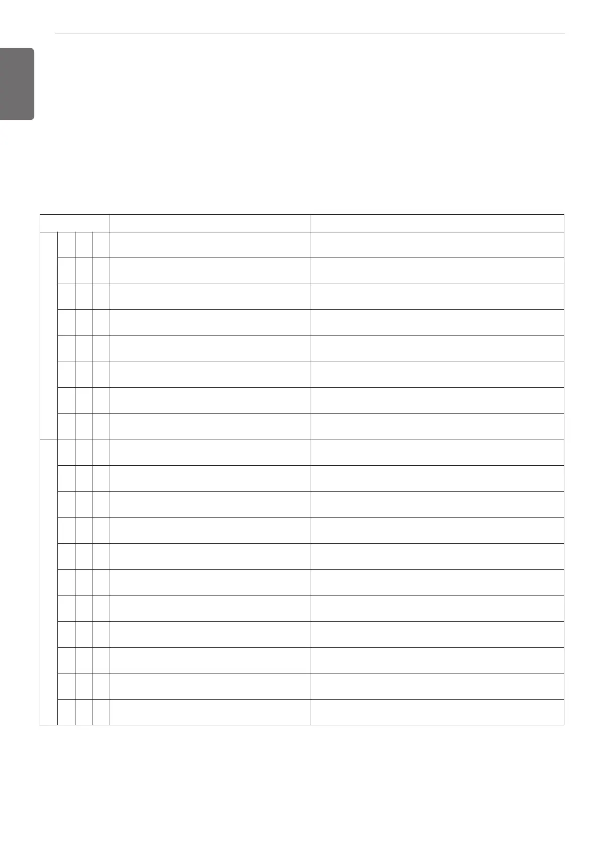
Self-Diagnosis Function
Error Indicator
- This function indicates types of failure in self-diagnosis and occurrence of failure for air condition.
- Error mark is displayed on display window of indoor units and wired remote controller, and 7-segment LED of outdoor unit control board as
shown in the table.
- If more than two troubles occur simultaneously, lower number of error code is first displayed.
- After error occurrence, if error is released, error LED is also released simultaneously.
Error Display
1st, 2nd LED of 7-segment indicates error number, 3rd LED indicates unit number.
Ex) 211 : No.21 error of unit
011 ’ 051 : No.105 error of unit
Display Title Cause of Error
Indoor unit related error
0 1 - Air temperature sensor of indoor unit Air temperature sensor of indoor unit is open or short
0 2 - Inlet pipe temperature sensor of indoor unit Inlet pipe temperature sensor of indoor unit is open or short
0 3 -
Communication error : wired remote controller ÷
indoor unit
Failing to receive wired remote controller signal in indoor unit PCB
0 4 - Drain pump Malfunction of drain pump
0 5 -
Communication error : outdoor unit ÷ indoor unit
Failing to receive outdoor unit signal in indoor unit PCB
0 6 - Outlet pipe temperature sensor of indoor unit Outlet pipe temperature sensor of indoor unit is open or short
0 9 - Indoor EEPROM Error
In case when the serial number marked on EEPROM of
Indoor unit is 0 or FFFFFF
1 0 - Poor fan motor operation
Disconnecting the fan motor connector / Failure of indoor
fan motor lock
Outdoor unit related error
2 1 1
Outdoor Unit Inverter Compressor IPM Fault
Outdoor Unit Inverter Compressor Drive IPM Fault
2 2 1
Inverter Board Input Over Current(RMS) of Out-
door Unit
Outdoor Unit Inverter Board Input Current excess (RMS)
2 3 1
Outdoor Unit Inverter Compressor DC link Low
Voltage
DC charging is not performed at outdoor unit after starting relay
turn on.
2 4 1 Outdoor Unit High Pressure Switch
System is turned off by outdoor unit high pressure switch.
2 6 1 Outdoor Unit Inverter Compressor Start Failure
The First Start Failure by Outdoor Unit Inverter Compressor Ab-
normality
2 9 1 Outdoor Unit Inverter Compressor Over Current Outdoor Unit Inverter Compressor Fault OR Drive Fault
321
Outdoor Unit Inverter Compressor High Discharge
Temperature
System is turned off by outdoor unit Inverter Compressor High
Discharge Temperature
3 4 1 High Pressure of Outdoor Unit
System is turned off by excessive increase of high pressure of
outdoor unit
3 5 1 Low Pressure of Outdoor Unit
System is turned off by excessive decrease of low pressure of
outdoor unit
3 6 1 Outdoor Unit Low Condensing Ratio Limited Outdoor Unit stayed under low condensing limit for 3 minutes
391
Communication error between Outside unit PFC
and inverter board
Outside unit inverter compressor current detection (CT) sensor
disconnection or short circuit
 Loading...