19
ENGLISH
Cool/Heat Selector Installation and Connec-
tion
Using Cool/Heat Selector Installation and Connection
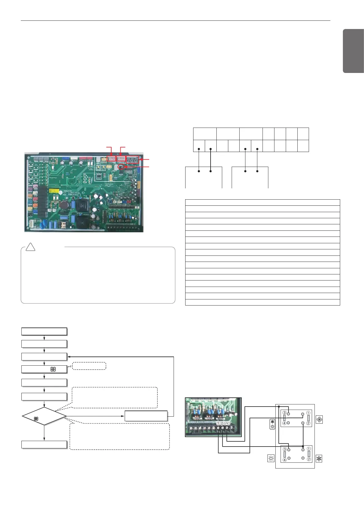
- Connect wires as below figure at the hole of backside of Outdoor
Unit Dry Contact.
- Insert the wire in the connection hole pushing the "Push" button.
- Maximum communication line length for Cool/Heat Selector : 200 m
(656 ft).
- Setting Main PCB Dip S/W of Master Outdoor Unit.
CAUTION
• In replacement of the indoor unit PCB, always perform auto ad-
dress setting again.
• If power supply is not applied to the indoor unit, operation error oc-
curs.
• Auto addressing is only possible on the main PCB
• Auto addressing has to be performed after 3 minutes to improve
communication.
!
The Procedure of Automatic Addressing
• Auto addressing setting end
Numbers of indoor unit connection set whose
addressing is completed are indicated for 30seconds
on 7-segment LED after completing setting
Indoor address number is displayed on wired remote control or
indoor unit display window. It is not an error message, will
disappeared when on/off button is pressed on remote control
ex) Display of 01, 02, ..., 15 means connection of 15 indoor
units and auto addressing is completed normally.
Auto addressing start
Waiting 3 minutes
Power On
Press SW02V for 5 sec.
7-segment LED = 88
Don't Press SW02V
Waiting about 2~7 minutes
7-segment LED
OK
YES
NO Check the connections
of communication line
= No. of IDUs
SODU IDU INTERNET DRY1 DRY2
B
A
B(D) A(C)
GND 12V
B
A
B
A
BA
Group recognizing the central controller
No.0 group (00~0F)
No.1 group (10~1F)
No.2 group (20~2F)
No.3 group (30~3F)
No.4 group (40~4F)
No.5 group (50~5F)
No.6 group (60~6F)
No.7 group (70~7F)
No.8 group (80~8F)
No.9 group (90~9F)
No. A group (A0~AF)
No. B group (B0~BF)
No. C group (C0~CF)
No. D group (D0~DF)
No. E group (E0~EF)
No. F group (F0~FF)
Main PCB
7 - Segment
SW02V
(Auto Addressing)
SW01B SW02B
Mode Change
Fan
Cooling
Back
Heating
Outdoor Unit
Group Number setting
Group Number setting for Indoor Units
- Confirm the power of whole system(Indoor Unit, Outdoor Unit) is
OFF, otherwise turn off.
- The communication lines connected to INTERNET terminal should be
connected to central control of Outdoor unti with care for their polar-
ity( A ’ A, B ’ B )
- Turn the whole system on.
- Set the group and Indoor Unit number with a wired remote control.
- To control several sets of Indoor Units into a group, set the group ID
from 0 to F for this purpose.
Outdoor Units (Terminal block on the main PCB)
Automatic Addressing
The address of indoor units would be set by auto addressing
- Wait for 3 minutes after applying power supply (main and sub outdoor
unit, indoor unit).
- Press the switch of the outdoor unit (SW02V) for 5 seconds.
- A "88" is indicated on 7-segment LED of the outdoor unit PCB.
- For completing addressing, 2~7 minutes are required depending on
numbers of indoor unit connection set.
- Numbers of indoor unit connection set whose addressing is com-
pleted are indicated for 30seconds on 7-segment LED of the outdoor
unit PCB.
- After completing addressing, address of each indoor unit is indicated
on the wired remote control display window. (CH01, CH02,
CH03, ............. CH06: Indicated as numbers of indoor unit connection
set.)
 Loading...