30
Multi V Wall-Mounted Indoor Unit
Due to our policy of continuous product innovation, some specifications may change without notification.
©LG Electronics U.S.A., Inc., Englewood Cliffs, NJ. All rights reserved. “LG” is a registered trademark of LG Corp.
General Guidelines — Gallery Indoor Units
Gallery indoor units have two options on how the piping and wiring can be routed: rear left or right.
• When choosing a location for the Gallery unit, be sure to take into consideration routing of wiring for power outlets within the wall. Contact-
ing wiring can cause serious bodily injury or death.
• Use caution when drilling holes through the walls for the purposes of piping connections. Power wiring can cause serious bodily injury or
death.
• Screws and anchors must be securely installed to prevent the chassis falling from its installation location. There is risk of injury from falling
equipment.
Note:
• Select the location carefully. Unit must be anchored to a strong wall to prevent unnecessary vibration.
• Mounting hardware must be securely installed to prevent the chassis falling from its installation location. There is risk of property damage
from falling equipment.
• Ensure the unit is properly installed. Incorrectly installed units can result in degraded performance or an inoperative unit / system.
• Use a level indicator to ensure the Gallery chassis is installed on a level plane.
• If the unit is installed near a body of water, certain components are at risk of being corroded. Appropriate anti-corrosion methods must be
taken for the unit and all components.
Preparing for Installation — Gallery Indoor Units
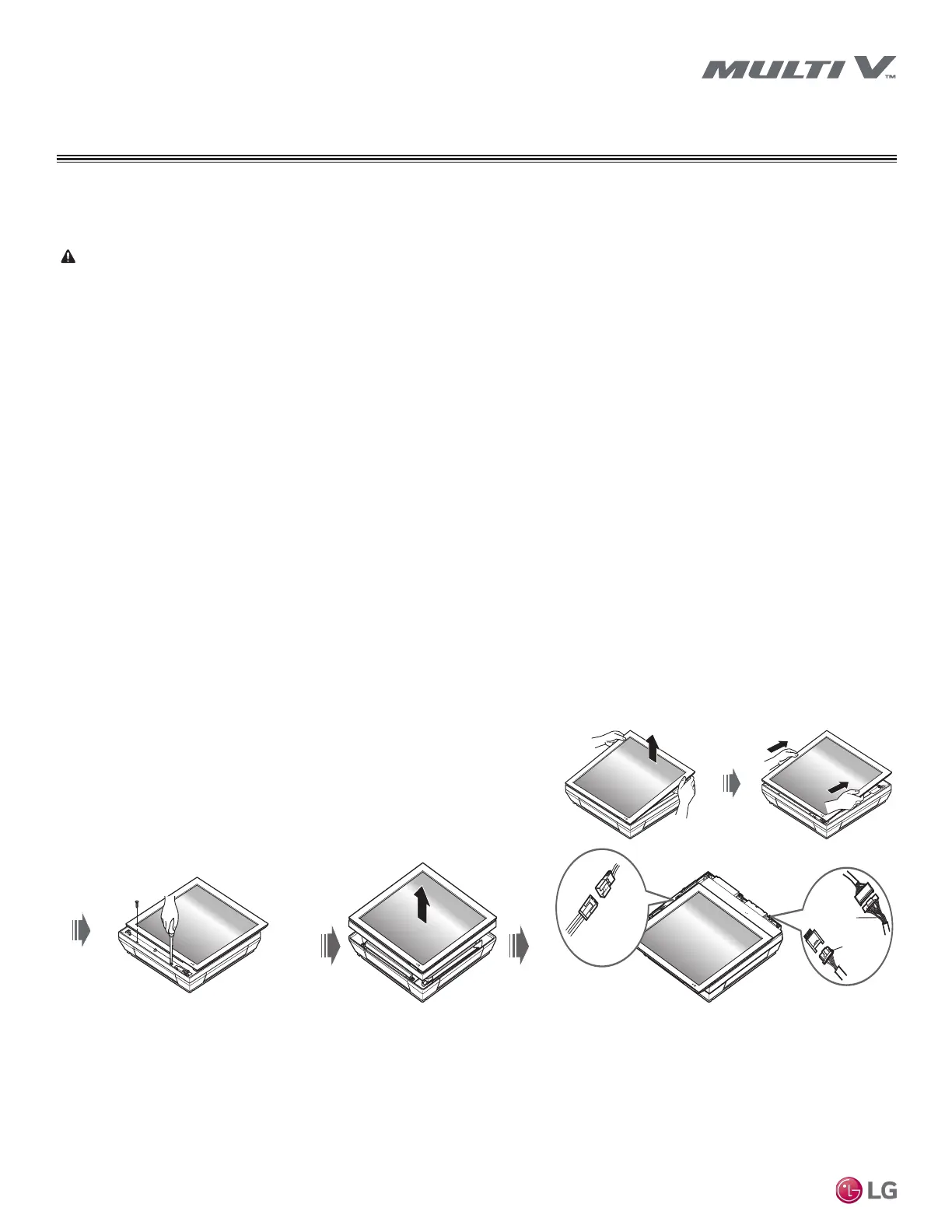
Detaching the Picture and Front Metal Panels
Before mounting the indoor unit to the wall, the front cover must be removed. Removal will allow the side holes to be knocked out, as well as
mounting the unit without damaging the front cover.
1. Lay the indoor unit on a flat surface, and then pull the upper part of the picture
panel away from the chassis (Step 1).
2. Lift up the picture panel so that the bottom part of the unit is visible (Step 2).
3. Detach the front metal cover by removing the two screws located at the bottom
(Step 3).
4. Disconnect the front metal panel connector at the top of the unit, then discon-
nect the Front Panel and Communication PCB connectors (Step 4).
Step 4
Front Panel
Connector
Comm. PCB
Connector
Comm. PCB
Connector
Figure 14: Detaching the Front Panel.
GENERAL INSTALLATION GUIDELINES
Gallery Indoor Units
SF Frame
 Loading...