Ceiling & Floor
Service Manual 41
8.1 Selection of the best location
• There should not be any heat source or steam near the
unit.
• There should not be any obstacles to the air circulation.
• There should be provision of easy condensate drain.
• Taking into accounting the noise prevention criteria, spot
the installation location.
• Do not install the unit near the door way.
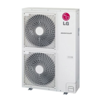
• Keep proper distances, of the unit, from ceiling, fence,
floor, walls and other obstacles as shown in figure.
• The indoor unit must have the maintenance space.
More than
20cm
More than eye-level
More than
20cm
R
R
More than
20cm
More than
20cm
(Ceiling installation)
(Floor/Wall installation)
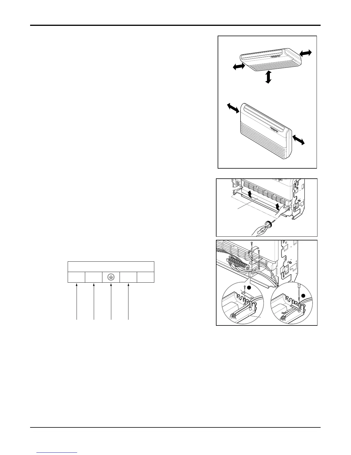
8.2 Wiring connection
1) Connecting cables to the Indoor Unit
1. Remove the Air guide - L by loosening 2 screws after
removing the Inlet grille from the Indoor unit.
2. Connect the wires to the terminals on the control board
individually according to the outdoor unit connection.
• Ensure that the color of the wires of outdoor unit and
the terminal No. are the same as those of indoor unit
respectively
AIR GUIDE-L
INDOOR UNIT
Control
Panel
1
2
Clamp
Terminal Block in Indoor
1(L) 2(N) 3 4
Connected to outdoor unit
2) Clamping of cables
1) Arrange 2 power cables on the control panel.
2) First, fasten the steel clamp with a screw to the inner boss of control panel.
3) For the cooling model, fix the other side of the clamp with a screw strongly.
For the heat pump model, put the 0.75mm
2
cable(thinner cable) on the clamp and tighten it with a plastic clamp to the
other boss of the control panel.
4) In Australia, the length of power supply cord measured from the entry of the power supply cord to the middle of live pin
on the power plug should be over 1.8m.
 Loading...