Section 1. Overview of the 7200-101 Flow Module
7200-101
1
1
2
3
7
8
4
5
6
7200-101
Flow Module
7200-101
Flow Module
7200-101
Flow Module
2
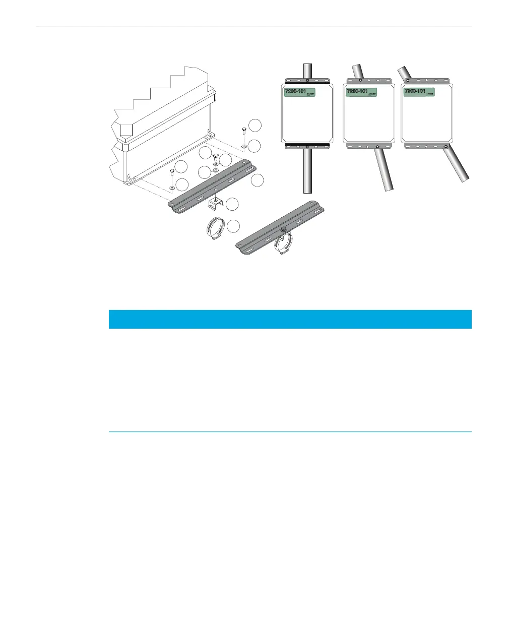
Figure 1-4. Attach mounting plates to the 7200-101, attach hose clamp mounting brackets
to mounting plates, and secure to mounting post using hose clamps.
Item Qty. Part Number Description
1 4 150-12943 M6x1 × 16 MM Hex Head Bolt
2 4 167-02054 Flat Washer 1/4 x 5/8”
3 2 167-05635 Split Washer 5/16”
4 2 235-13234 Single Bolt Flared Leg Mounting Bracket
5 2 300-13293 Hose Clamp, 9/16”
6 2 9879-045 Mounting Plate
7 2 included w/ item #4 5/16-24 × 1/2” Hex Head Bolt
8 2 included w/ item #4 5/16” Flat Washer
Table 1-1. Mounting kit parts.
There are some additional considerations that should be taken into account when
locating the Flow Module, including:
l The Accessory cable that connects to the LI-7550 Analyzer Interface Unit is 5
meters long. Determine the height at which the LI-7550 and LI-7200/RS sensor
head will be mounted, and plan to mount the Flow Module accordingly.
l The thermal properties of the Flow Module are such that it is OK to place the
box in direct sun.
1-6 7200-101 Flow Module