More user manuals on ManualsBase.com
Operation
12
4.0 OPERATION
4.1 Block Diagram
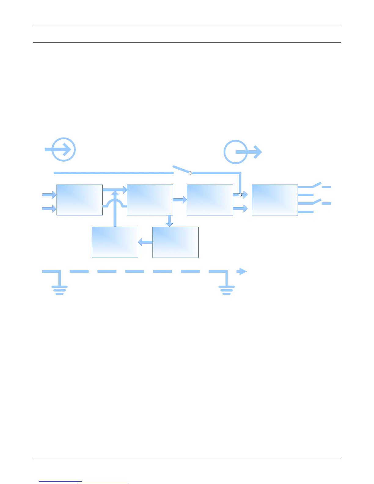
The Liebert
®
GXT3-10000T220
™
consists of the following main components:
• 2 utility inputs with separate breakers—utility and bypass
• rectifier/booster, inverter and charger
• electronic bypass
• 2-position Maintenance Bypass Breaker—UPS and BYPASS
• integrated battery
Figure 9 System block diagram
TVSS &
EMI/RFI
Filters
Rectifier/
PFC
DC-to-DC
Converter
Inverter
Isolation
Transformer
Battery
Battery
Charger
L1
N
L1
N
X1
X3
X4
X2
OutputInput
Dynamic
Bypass
V bp
G G






 To Next Page