Hiflex
70 -W- Version
English
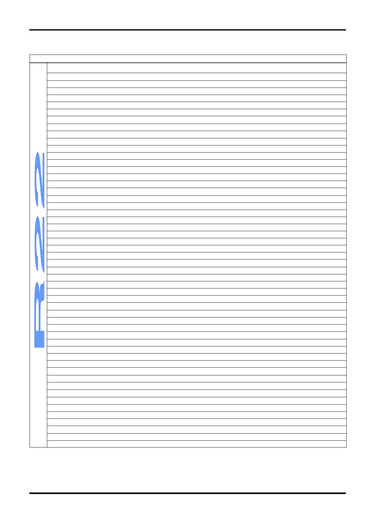
Technical data and performances-water condensation -xxOW series, upward flow-60Hz
MODEL 5SOW 5LOW 7SOW 7LOW 9SOW 9LOW
power supply voltage V/ph/Hz
208-230/1
/60
200-230/3
/60
200-230/3
/60
380/3/60 380/3/60 380/3/60
PERFORMANCES
(1)
air flow m
3
/s 1.00 1.22 1.54 1.70 2.10 2.56
available head Pa 50 50 50 50 50 50
fans absorbed power kW 1.0 2.0 1.4 1.6 2.2 2.8
each fans absorbed current A 2.1 4.1 3.3 3.7 5.1 6.2
sound pressure level
(2)
dB(A) 52.4 54.7 53.7 62.7 53.9 58.9
condenser inlet water temperature: 15°C; condensation temperature: 40°C
total cooling capacity kW 13.0 19.0 24.4 28.2 31.4 39.0
sensible cooling capacity kW 11.2 15.4 21.0 23.6 27.2 32.8
full absorbed power (fans and compressors) kW 4.0 6.4 6.6 7.8 8.6 10.6
compressors absorbed power kW 3.0 4.4 5.4 6.4 6.4 7.8
each compressors absorbed current A 5.9 6.1 7.3 5.6 5.6 7.0
SHR (Sensible Heat Ratio) - 0.87 0.81 0.86 0.84 0.87 0.84
EER (Energy Efficiency Ratio) - 3.29 2.96 3.66 3.59 3.66 3.67
water flow l/s 0.12 0.20 0.22 0.28 0.30 0.40
water pressure drop kPa 1 3 2 2 3 4
condenser inlet water temperature: 30°C; condensation temperature: 45°C
total cooling capacity kW 12.6 18.2 23.8 27.4 30.4 37.6
sensible cooling capacity kW 11.0 15.0 20.6 23.2 26.8 32.2
full absorbed power (fans and compressors) kW 4.2 7.0 7.2 8.6 9.2 11.6
compressors absorbed power kW 3.4 5.0 6.0 7.0 7.0 8.6
each compressors absorbed current A 6.5 6.6 7.9 5.9 5.9 7.4
SHR (Sensible Heat Ratio) - 0.88 0.82 0.87 0.85 0.88 0.86
EER (Energy Efficiency Ratio) - 2.93 2.63 3.27 3.19 3.28 3.25
water flow l/s 0.26 0.46 0.50 0.64 0.72 0.98
water pressure drop kPa 5 13 6 9 12 21
FANS
quantity no. 2 2 2 2 2 2
type - dd 9/9 dd 9/9 dd 10/10 dd 10/10 dd 12/12 dd 12/12
speed no. 3 3 3 3 3 3
nominal power kW 0.245 0.420 0.500 0.500 0.736 0.736
poles no. 6 4 6 6 6 6
COMPRESSORS
quantity/type 2/scroll
nominal power for each compressor HP 1.90 2.50 3.25 4.00 4.00 5.00
refrigerant R22 R22 R22 R22 R22 R22
EVAPORATING COIL
pipes/fins copper/aluminium copper/treated aluminium
fins for inch/rows no. 12/3 12/3 12/4 12/4 12/5 12/5
front surface single coil m
2
0.33 0.33 0.50 0.50 0.50 0.50
position/quantity inclined/2
CONDENSER
quantity/type - 2/plate
water connections inch ½" BSP
DIMENSIONS
length mm 1490 1490 1490 1490 1490 1490
depth mm 450 450 600 600 750 750
height mm 1950 1950 1950 1950 1950 1950
plan surface m
2
0.67 0.67 0.89 0.89 1.12 1.12
WEIGHTS
net kg 355 385 405 435 555 585
gross kg 375 405 425 455 575 605
1 ON THE FOLLOWING STANDARD CONDITIONS: standard supply [voltage 10%]; room conditions 24°C bs; 50% R.H. (17°C bu)
2 Measured in the front part at 1 m height, 2 m distance, referred to free field, with working fans and compressor.
ATTENTION: the refrigerating outputs are meant after deduction of the heat taken from the fans, which must thus be added to the room load. The EER
refers only to the room unit. The unit air flow refers in standard configuration with clean class filter G3.