Hiflex
90 -C- Version
English
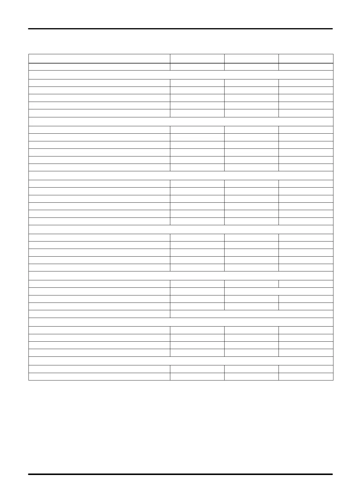
Technical data and performances - chilled water unit -xxUC series, downward flow -60H
MODEL 4LOC 6LOC 8LOC
power supply voltage V/ph/Hz 230/1/60 380/3/60 380/3/60
PERFORMANCES
(1)
air flow m
3
/s 0.61 0.85 1.28
available head Pa 50 50 50
fan absorbed power kW 1.0 0.8 1.4
fan absorbed current A 4.1 3.7 6.2
SPL (Sound Pressure Level)
(2)
dB(A) 51.7 59.7 55.7
coil inlet water temperature: 7°C; outlet water temperature: 12°C
total cooling capacity kW 7.2 12.0 17.0
sensible cooling capacity kW 6.6 10.7 15.7
water flow l/s 0.341 0.573 0.813
coil pressure drop kPa 15 14 15
total pressure drop kPa 25 25 23
SHR (sensible heat ratio) - 0.92 0.89 0.92
coil inlet water temperature: 10°C; outlet water temperature: 15°C
total cooling capacity kW 5.0 8.3 12.1
sensible cooling capacity kW 5.0 8.3 12.1
water flow l/s 0.238 0.396 0.579
coil water pressure drop kPa 8 8 9
total water pressure drop kPa 13 13 13
SHR (sensible heat ratio) - 1.00 1.00 1.00
FANS
quantity no. 1 1 1
type dd 9/9 dd 10/10 dd 12/12
speed no. 3 3 3
nominal power kW 0.420 0.500 0.736
poles no. 4 6 6
CHILLED WATER COIL
quantity no. 1 1 1
pipes/fins copper/aluminium copper/treated aluminium
fins for inch/rows no. 12/3 12/4 12/5
front surface m
2
0.33 0.50 0.50
position inclined
DIMENSIONS
length mm 750 750 750
depth mm 450 600 750
height mm 1950 1950 1950
plan surface m
2
0.34 0.45 0.56
WEIGHTS
net kg 145 175 255
gross kg 155 185 305
1 ON THE FOLLOWING STANDARD CONDITIONS:
standard supply [voltage 10%]; room conditions 24°C bs; 50% R.H. (17°C bu)
2 Measured in the front part at 1 m height, 2 m distance, referred to free field.
ATTENTION: the refrigerating outputs are meant after deduction of the heat taken from the fans, which must thus be added to the room load. The
unit air flow refers to high speed, in standard configuration with clean class filter G3.